Electron Ultra v5
The version that I wasn't going to make..but that tiny error on the 2nd processor header has been niggling me for quite a few months.
I did correct the PCB design in v4.01 (which I have never ordered) but then came my little RAM replacement board and that has triggered further thought on else could be done to make it worth while for a v5 build.
I looked back at my previous versions to see if I'd noted any additions I'd like to make but didn't. Way back at v2 (June 2024) I made this list below:
Add:
A joystick Port - possibly not?
Remove:
The UHF modulator
The Cassette interface
Remove composite video port
Remove the audio port (I added)
Remove the Printer Port?
The joystick port is the only item I've not added since then and from what I've read it seems joystick support is a bit patchy in Electron games so I think I'll leave it off. A joystick cartridge can still be used if needed.
The 'Remove' list has hardly been touched mainly because there was very little point in making these changes. I only removed the expansion connector out of necessity to allow space for the Econet components.
Looking at that list, if I remove these items I could bring the PCB back to its original size of Micro ATX, 9.6" x 9.6" and I could add a PCB mounted speaker. I think that's a big enough change to justify a new build.
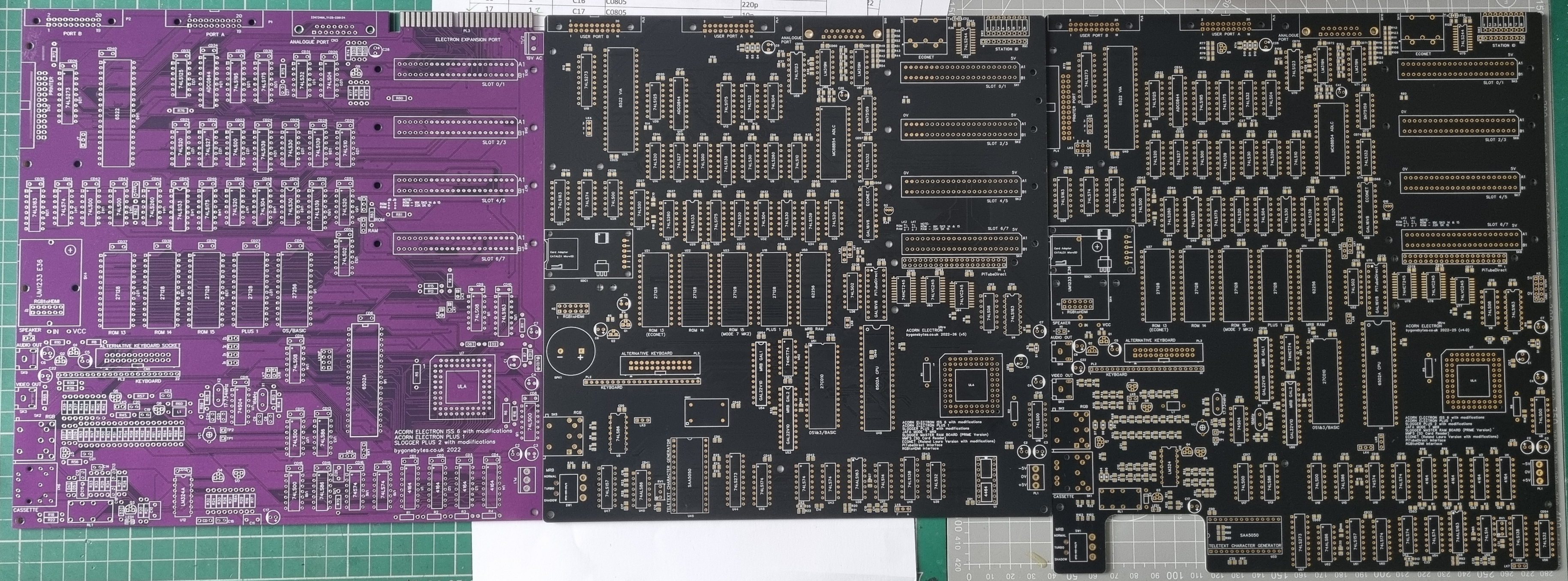
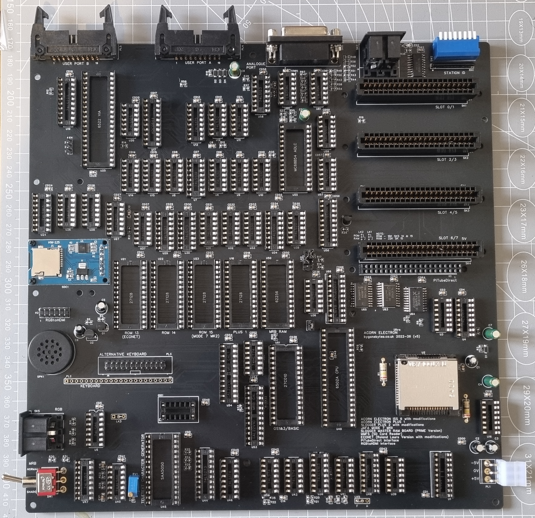
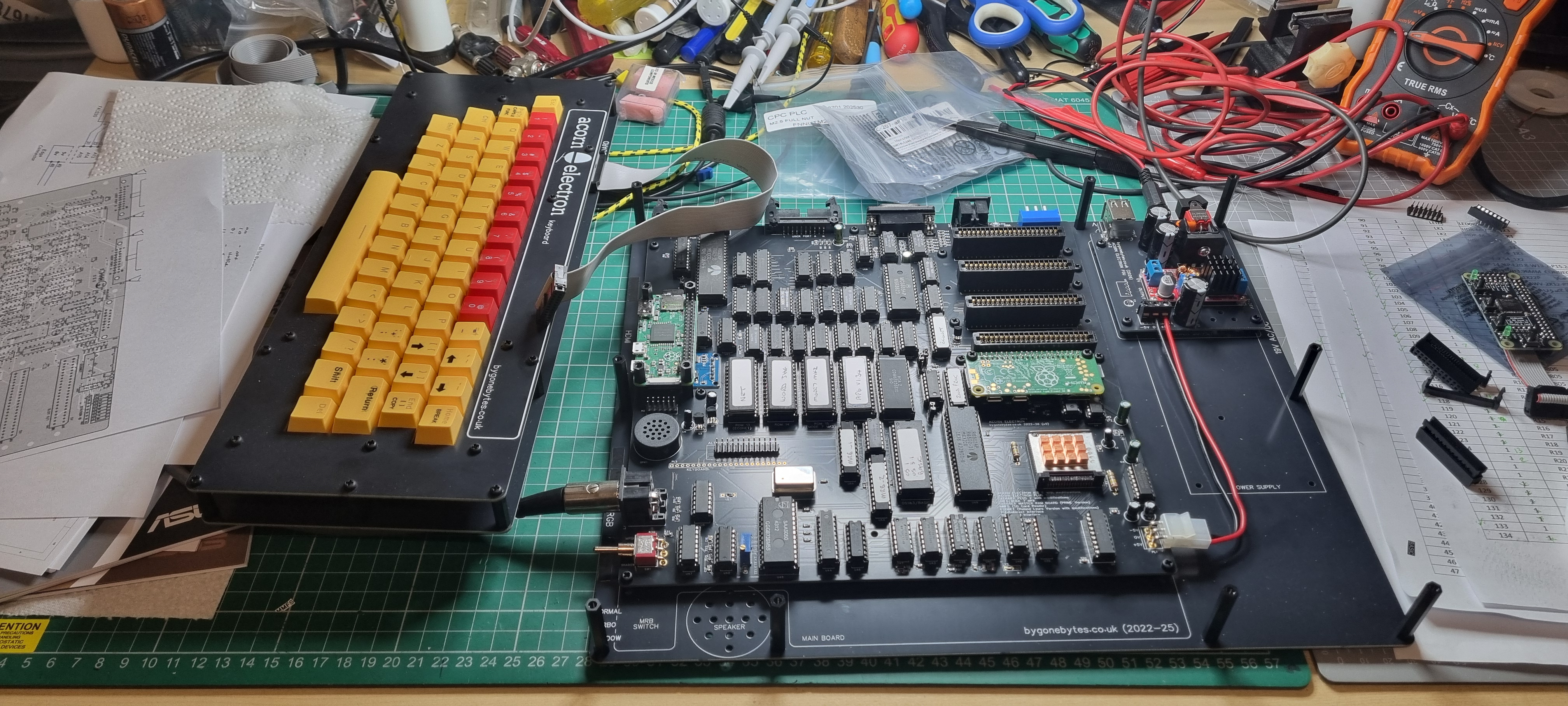
The centre PCB is the new board layout and at first glance it doesn't look much different from my first (purple) PCB although there is a huge difference in functionality. I've included the v4 PCB so the size reduction can be seen.
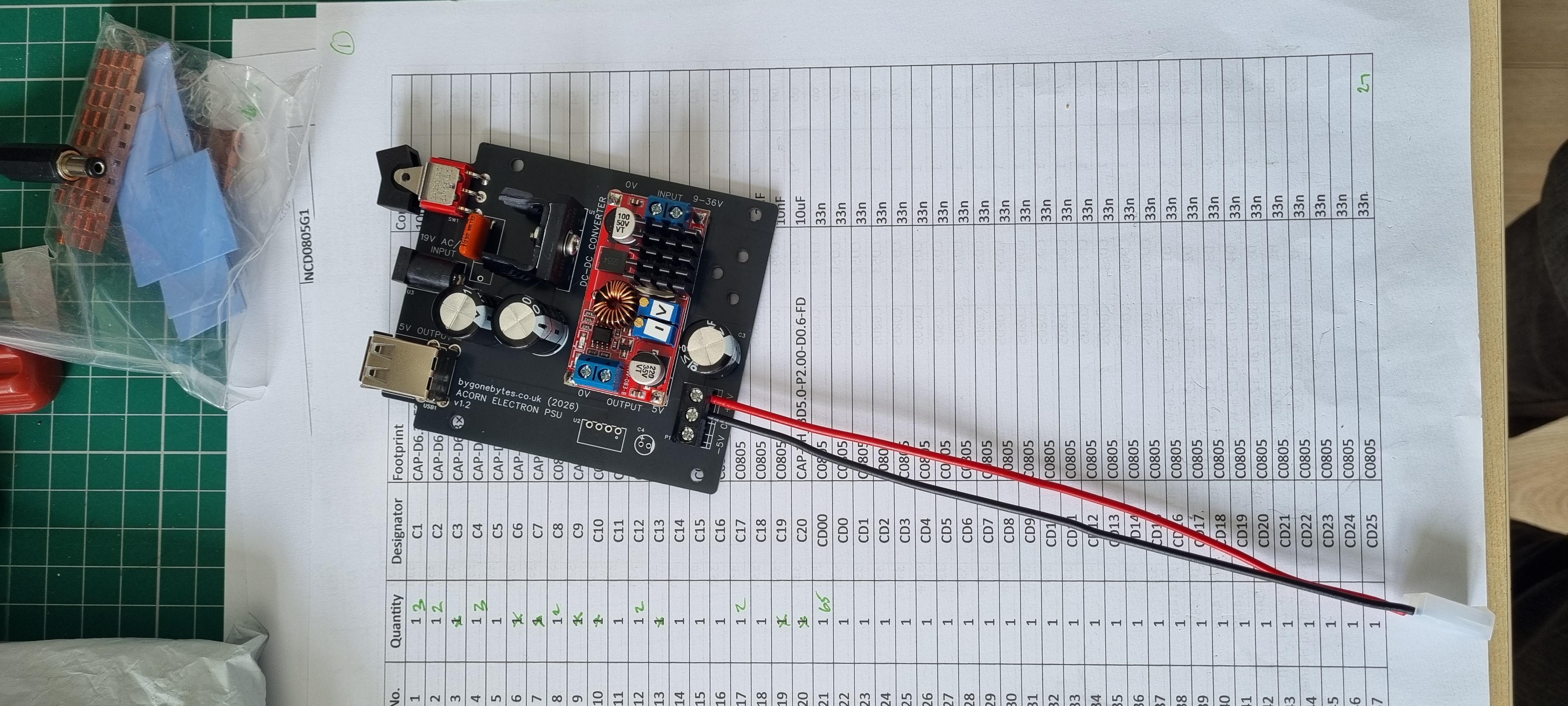
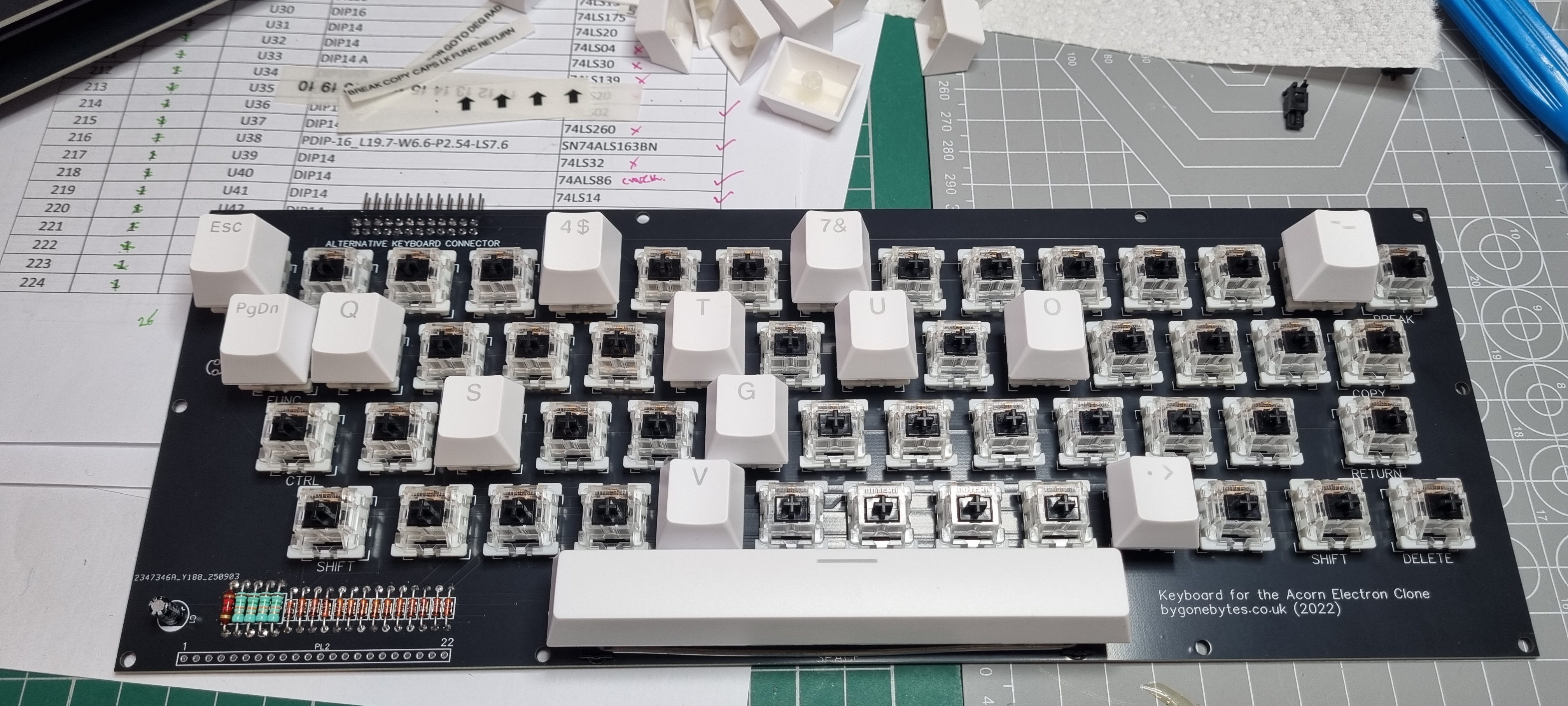
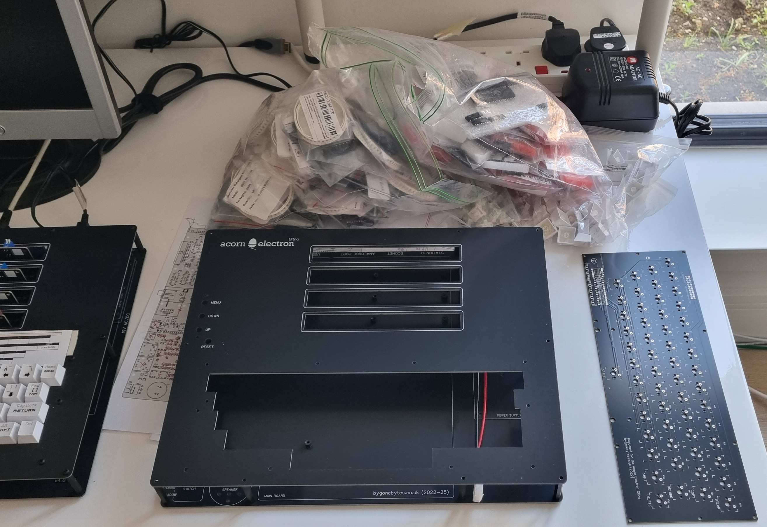
I went through my usual process of building a case, PSU, keyboard and looking out the components required for the PCB - just a few short so I ordered them in time for the arrival of the PCB.
This time the build was a lot quicker as there were considerably less surface mount components to solder. I decided to fully build before testing.. getting more confident that it'll work.
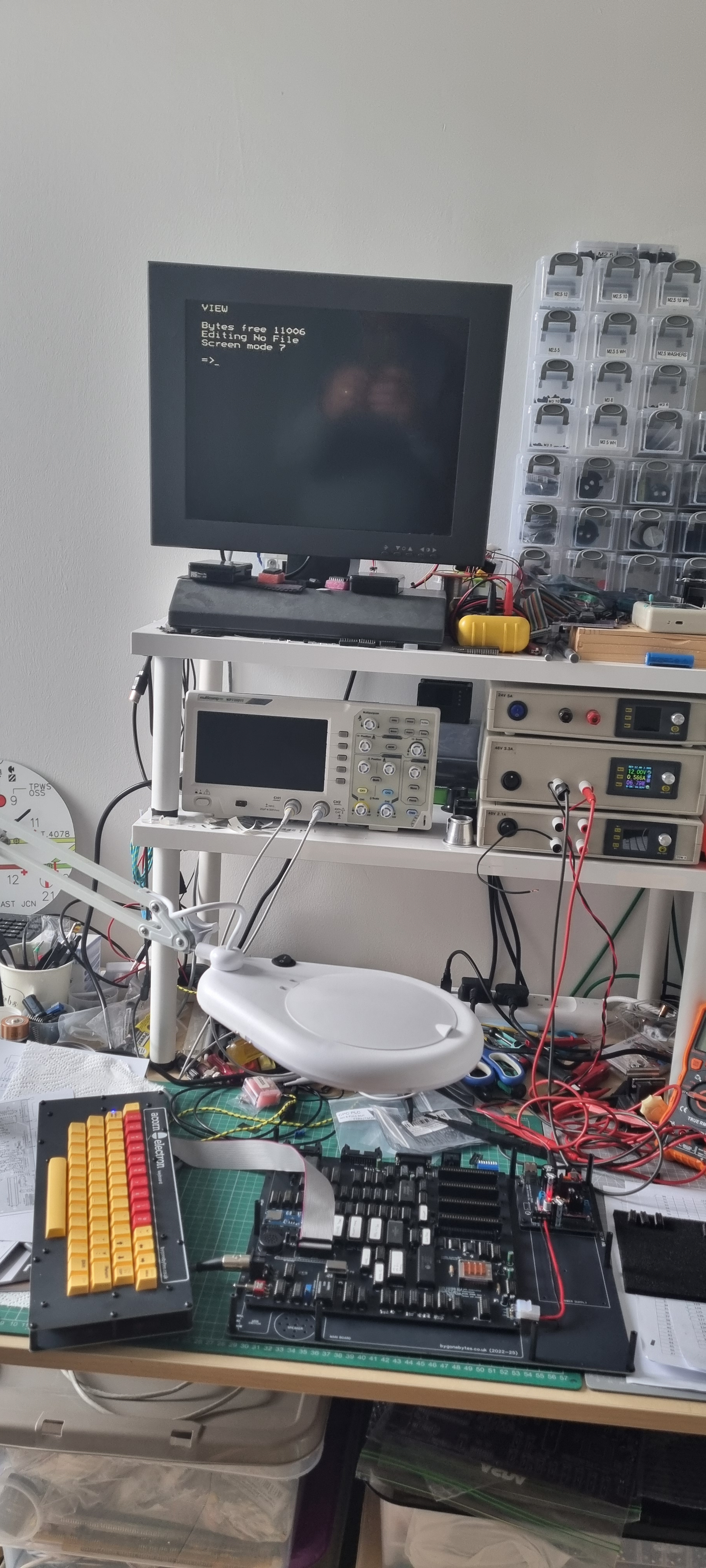
The first test I always do is to check the oscillators, this time it is just the one, 16MHz and this is what it looks like.
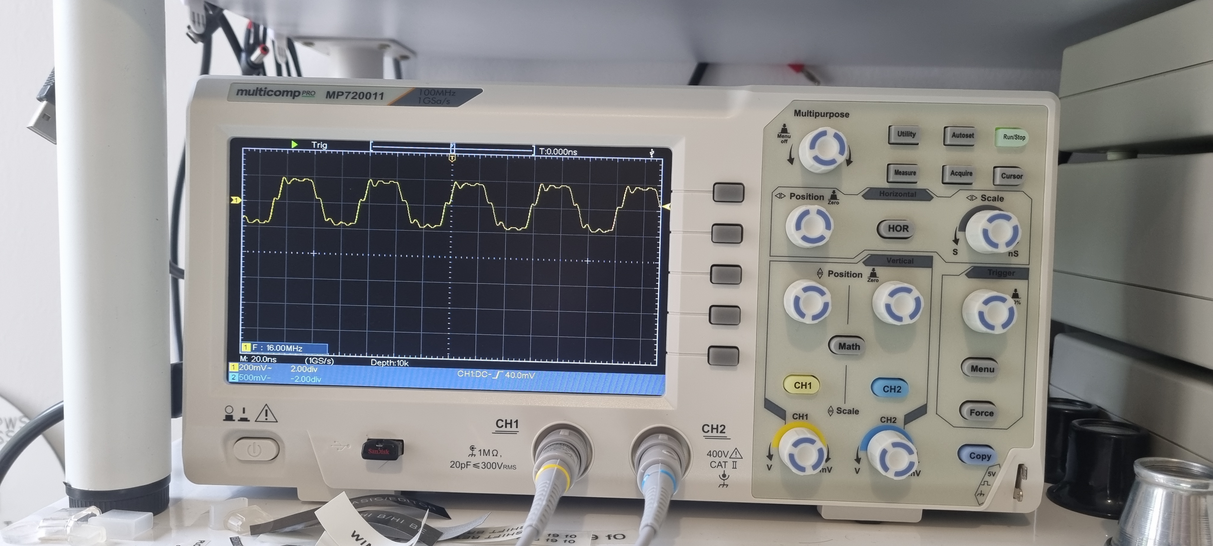
I was expecting the wave form to be a bit cleaner but it's a lot better than the original 74S04 oscillator.
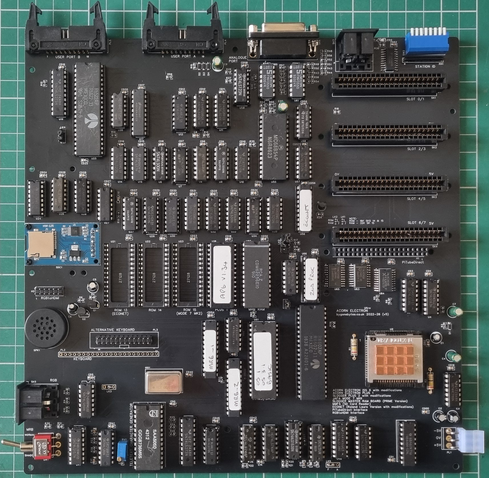
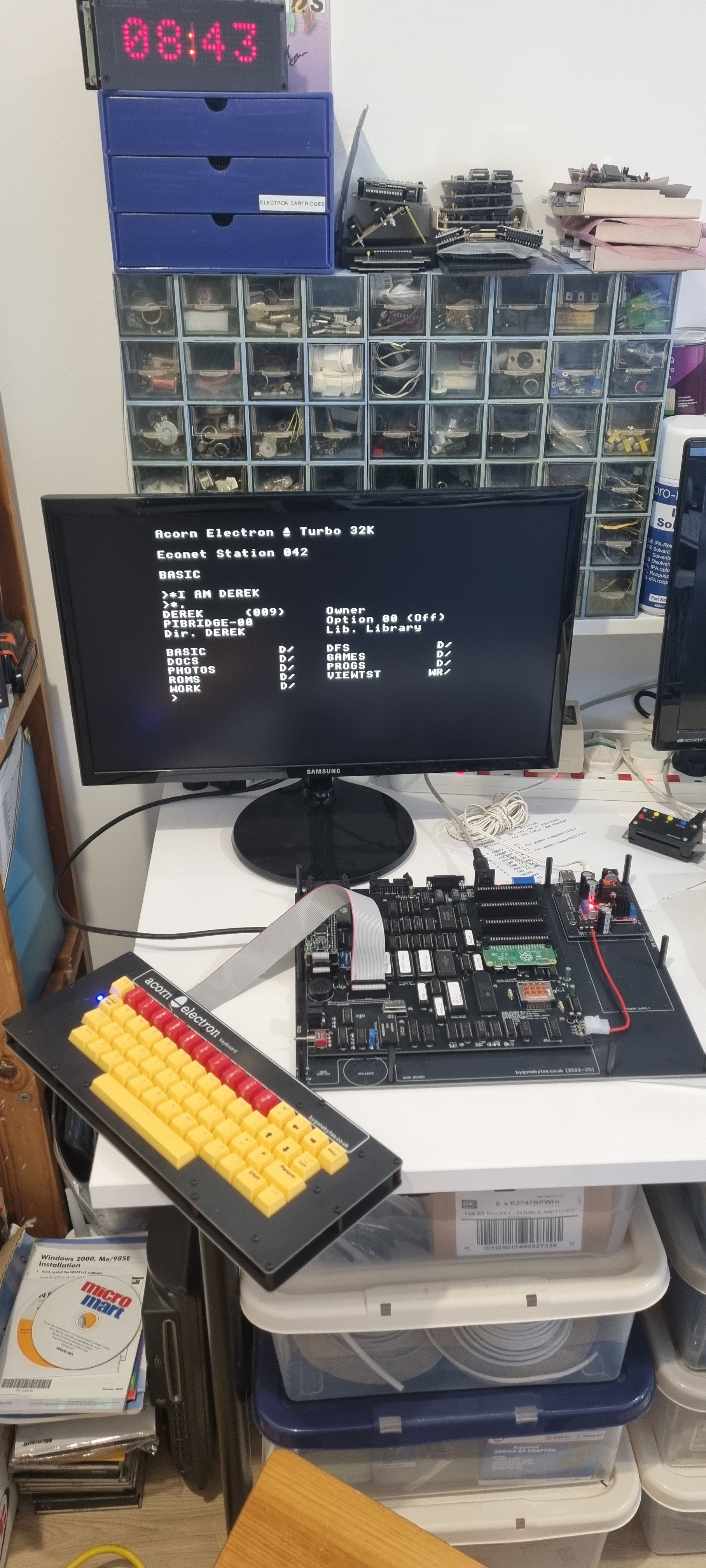
Fully populated and ready to switch on.. and it came up with the power on banner first time - it sounds different without the relay click. Still a lot of testing to do.
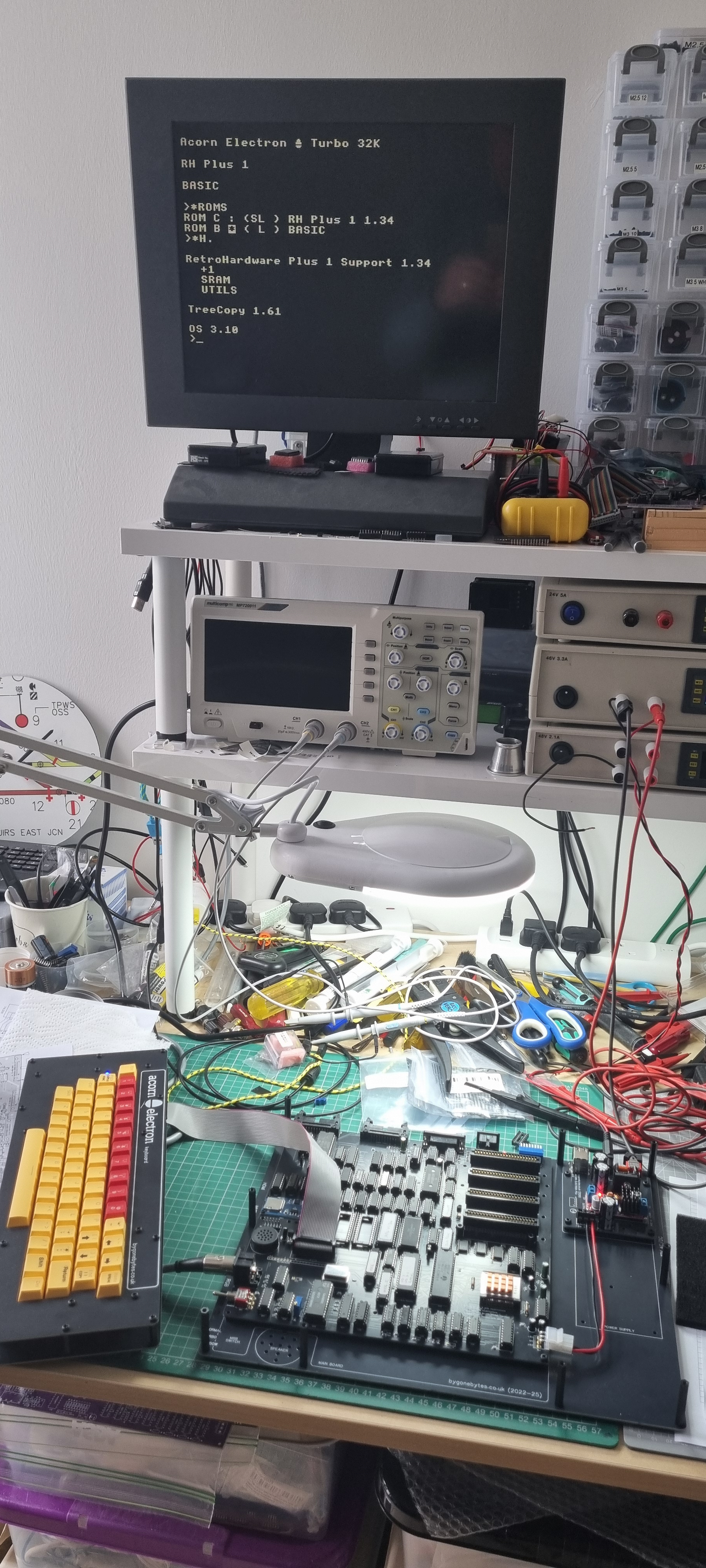
Next up is adding my usual ROM's, Mode7 Mk2, Econet, and View then tuning in the Mode 7 screen using the pot.
Then adding the PiTubeDirect Co-Processor and RGBtoHDMi and finally testing the Econet and keyboard..
A build can't go this smoothly.. I found that the 3, E, D, and C keys didn't work. On investigation I discovered I had put the column diode in the wrong way round.
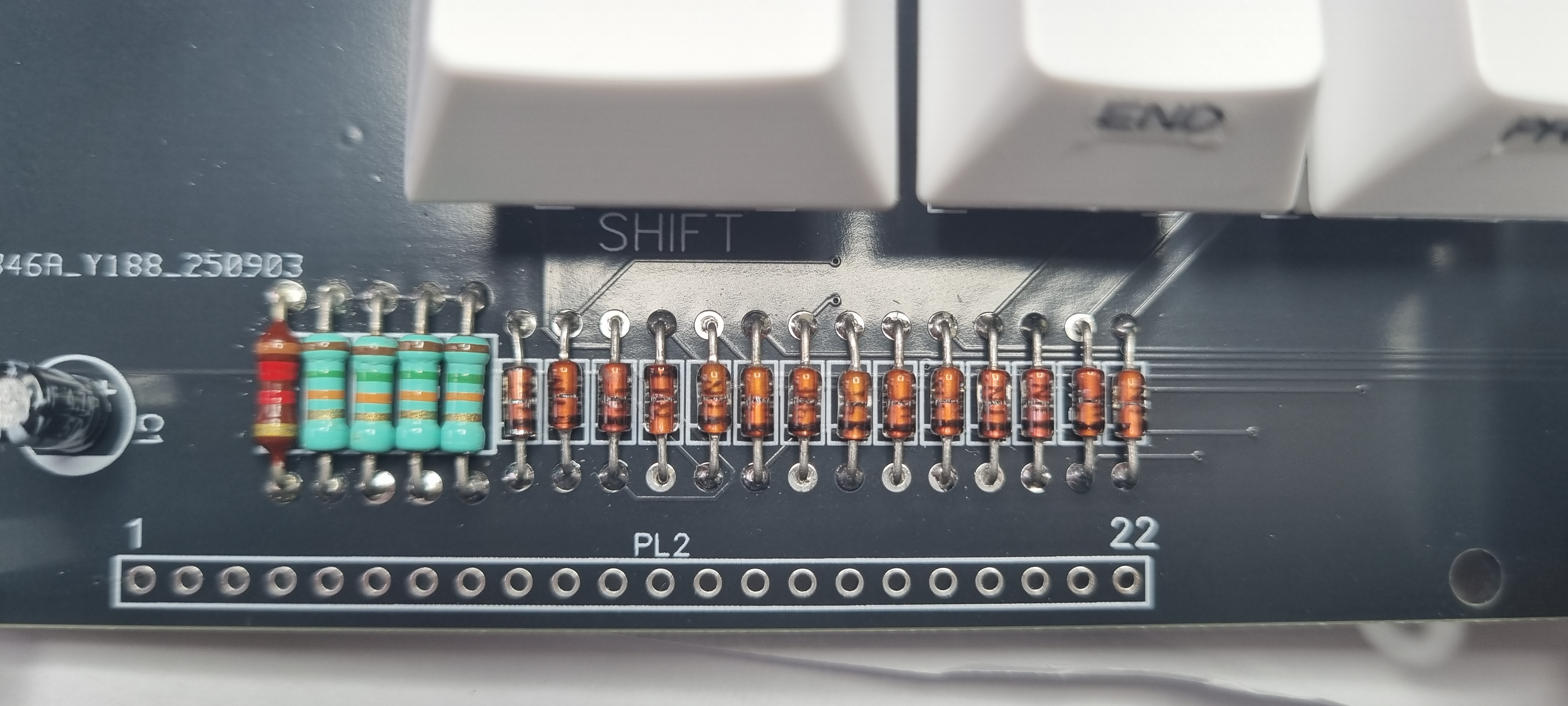
D4 is the culprit, fourth diode from the left. A quick swap round and it now works fine.
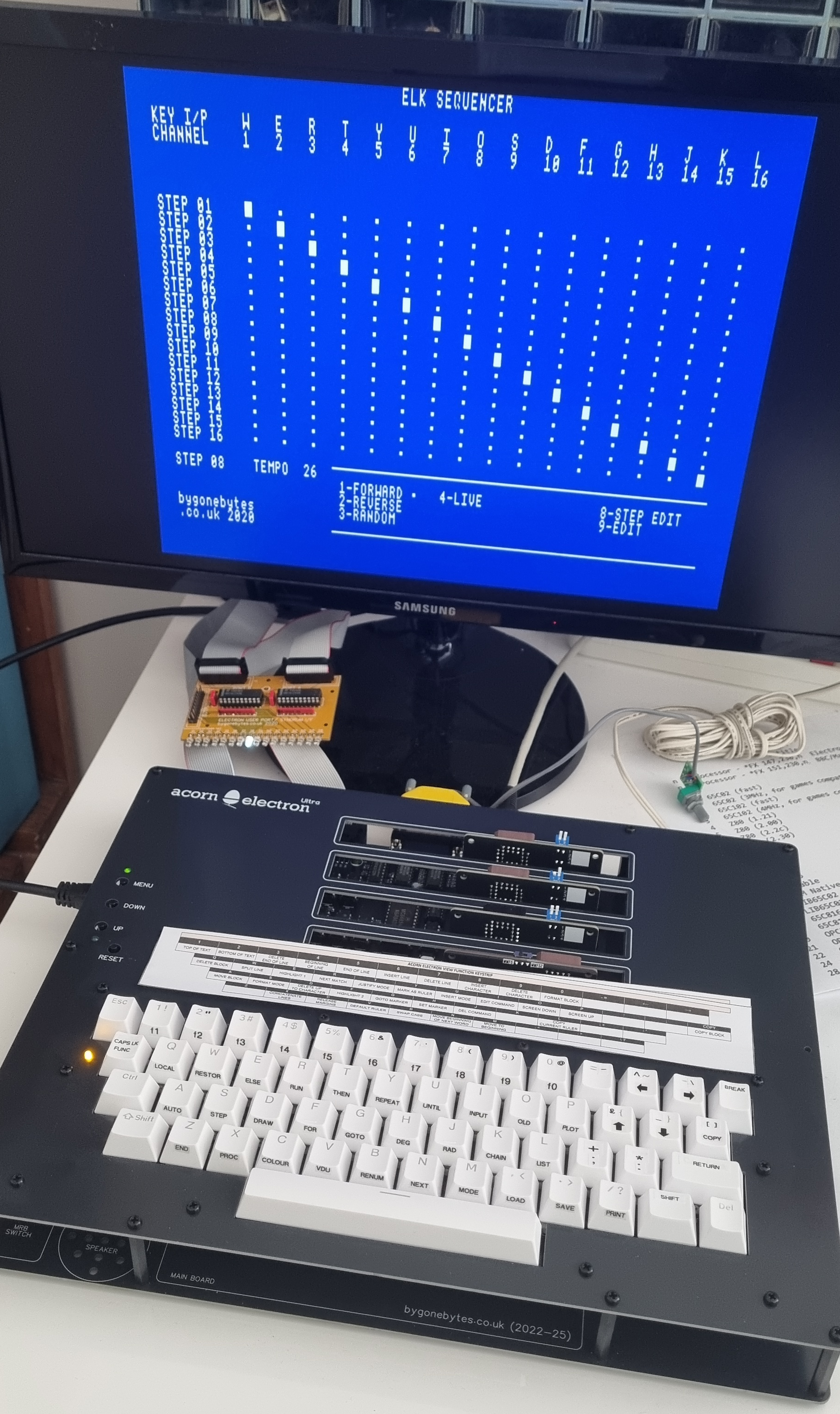
The final test required was to show the User and Analogue Ports work so using my sequencer program I tested each user port output and the analogue inputs (uses a potentiometer to set the tempo).
Here's the list of changes from version 4 to version 5:
Removed the cassette interface.
Removed the composite video and UHF circuits.
Removed the printer socket - port only used for MMFS.
Removed unused links.
Removed the original oscillators (74S04) and replaced it with a 16MHz oscillator module.
Removed the four TMS4164 RAM chips and replaced them with one TMS4464 RAM chip - much more reliable.
Added a PCB mounted speaker.
Moved the keyboard connectors to give more room between the keyboard socket and the PCB socket - more space for the ribbon cable to pass between them.
Fixed the error on the PiTubeDirect socket.
Changed a few componet types from LS to HCT - just what I had available.
Cleared tracking from under the Micro SD card so it can sit directly on the board - no more washers.
Possibly this time it will be my last iteration of the Ultra PCB as there are no more niggling errors and I have run out of ideas for updates.