Relay Contact Timer - 1980
 Sometimes there are requirements in the relay logic to delay a relay before it picks or drops and this was usually done with a resistor/capacitor network. To get an
accurate time I designed a simple counter that was triggered from the front and back contacts of the relay. It counted up in 1/10th seconds.
Sometimes there are requirements in the relay logic to delay a relay before it picks or drops and this was usually done with a resistor/capacitor network. To get an
accurate time I designed a simple counter that was triggered from the front and back contacts of the relay. It counted up in 1/10th seconds.It was built with the up and coming technology of Liquid Crystal Displays and used CMOS logic to ensure that the unit was portable and battery life was extended compared to the common LED/TTL equivalent.
Building it into a dicast case made for ruggedness with a handle that was mounted offset to the centre for comfortable carrying due to the battery weight being toward one end. Only one was built which was sent out into the field and was never seen again..I hope it was put to good use.
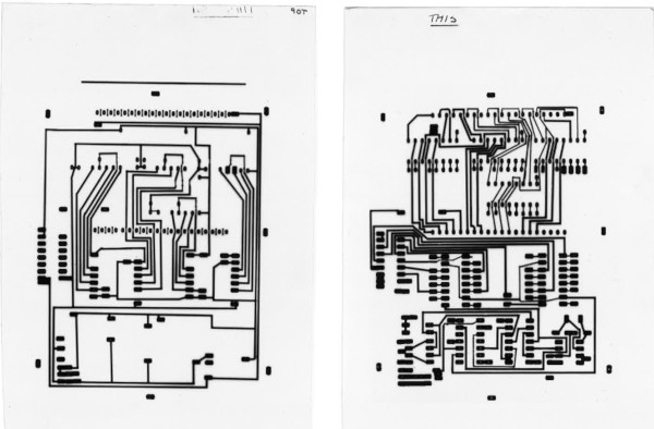
The PCB was designed double sided using etch resist transfers on acetate and was photo etched and drilled in house. At this time we didn't have an Ultraviolet lightbox or eching tank - what we had to do was spray the copper clad board with photo sensitve varnish and bake dry in a dicast box with a soldering iron for a heat source then used the sun as an ultraviolet light source and finally used photographic trays for the Sodium Hydroxide and ferric chloride baths. It got a lot more simpler in the years ahead..
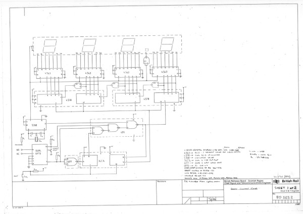
Section Failure Locator - 1981
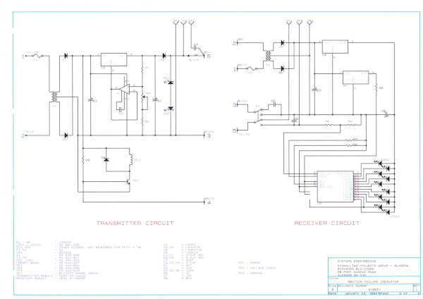
 We had just installed a CCTV transmission system between Halbeath and Edinburgh Waverley SC, this covered a distance of around 32Km. The system was made by Marconi and used a 14MHz AM carrier over
coax. Due to the distances the carrier had to be amplified every 3 to 4Km so a repeater was used to re-launch the signal at 12Vp-p. Having around ten reapeater would cause a maintenance
issue if any one of them should fail - where do you start looking? It would be a very time consuming job to track down the offending repeater.
We had just installed a CCTV transmission system between Halbeath and Edinburgh Waverley SC, this covered a distance of around 32Km. The system was made by Marconi and used a 14MHz AM carrier over
coax. Due to the distances the carrier had to be amplified every 3 to 4Km so a repeater was used to re-launch the signal at 12Vp-p. Having around ten reapeater would cause a maintenance
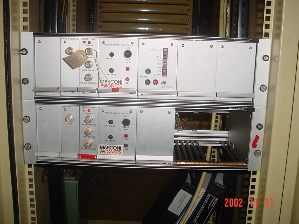
issue if any one of them should fail - where do you start looking? It would be a very time consuming job to track down the offending repeater.Luckily each repeater had a small relay that would drop out if a loss of carrier was detected. Under fault conditions we used this to put a DC voltage on to the coax which was extracted at the demodulator in Edinburgh Waverley RR to be displayed on a LED volt meter (LM3914). The setup was simple, we put a diode protected power supply in each location 1/2V higher than the next, lowest voltage nearest Edinburh, highest at Halbeath. If a carrier was lost at any location all the other locatations from that point would put its voltage on to the coax, the highest would win out lighting the corresponding LED at the receiver - each LED was labelled with a location number. This would indicate to the Technician that the fault was either at the indicated location or the one in rear (or the cable in between) cutting down the time taken to locate the fault.
The power supplies and volmeter were built into Marconi card frame modules and slotted into a spare position to keep the installation neat and tidy.
10 Second Annunciator - 1982
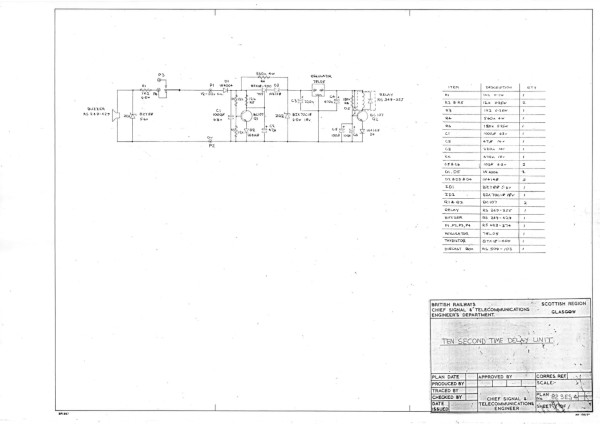 The 10 second annunciator was used on the signallers block shelf to sound a buzzer for 10 seconds after the power has been applied and had to work over a voltage range of 12-50V. This what we came up with..
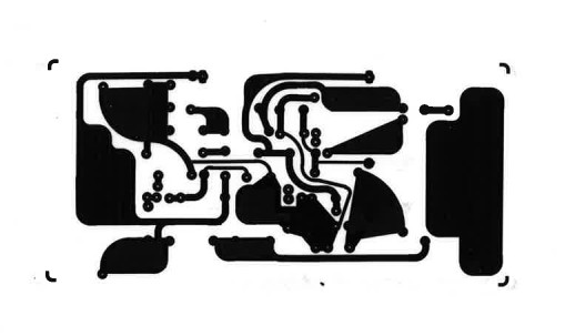
Relay Contact Tester - 1982
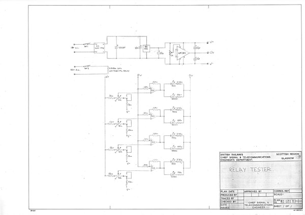 High resistance relay contacts have been a problem for a long time in the rail industry so we came up with this voltage comparitor solution. I'm not sure how reliable it turned out to be..
TD Display Module Tester - 1985
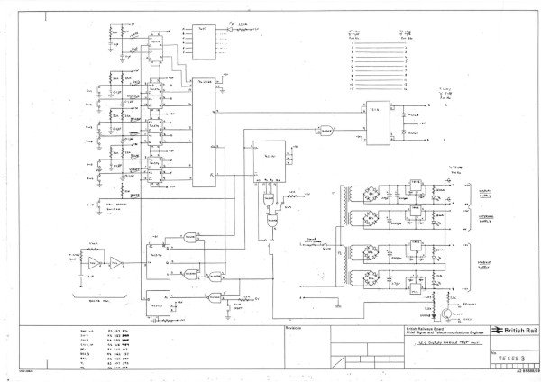
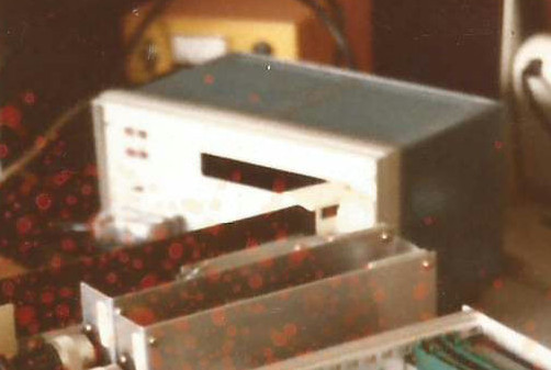
After designing the train describer display module we needed a simple way to test each one so we built a small box with power supplies and the logic to stream the data to the module. This is the only photo that I can find of the Unit.
It had been modified over the years - our TD modules accepted train description characters using an 6 bit binary pattern so the box had six buttons to send one character at a time. However the Train Describer concatinated the four characters of a description into three 8 bit messages to save transmission time so this lead to the original circuit/button PCB being removed (you can see the empty key slot in the photo) with an external eight key keyboard being plugged into the unit.
Later it was again modified to be controlled from the MDS so we could display a scrolling Xmas message to staff passing our office. We even modified the character set on one display module to have a flashing chrismas tree and displayed it on a red LED matrix.
During 2021 I spend some time refurbishing some TD display modules and built a new version of the Display Tester to make this short video:
Modem Racks - 1990/94
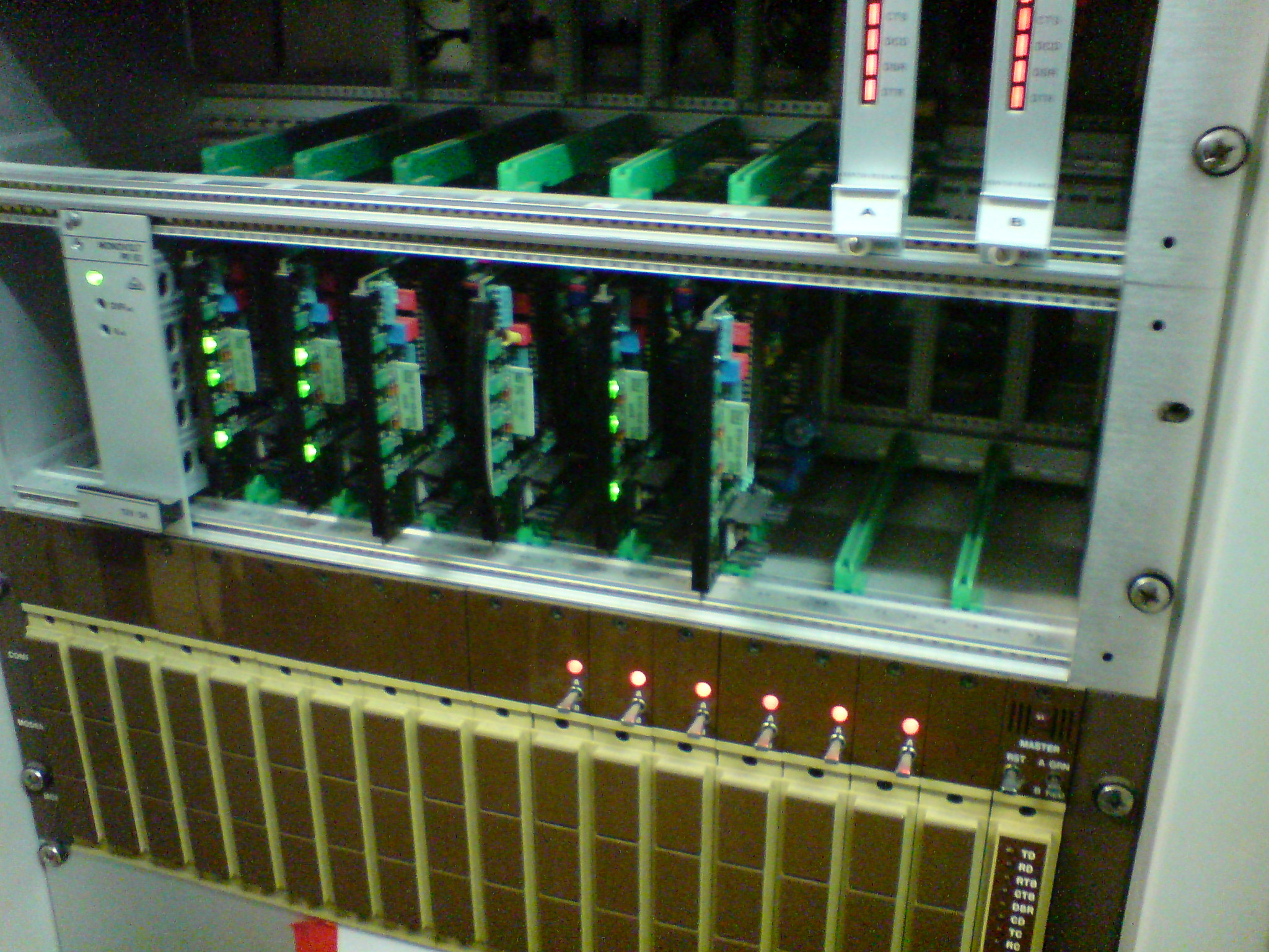 Two Modem Racks were built, one for Yoker and the other for Edinburgh Waverley. Eight single eurocard modems, 82SES2, built into a single 3U rack with a Vero PK60 12V PSU.
The photo shows the Yoker modem rack, the modems carried the TD link to Glasgow Central, the TRUST link to Queen St. and the two TDM links to Craigendorran.
Modem Monitor Module - 1990
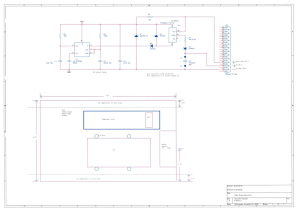
 The Modem Monitor Module was made as an accessory for our FELINE data line monitor. The module allowed us to eavesdrop directly on the VF lines (1200 Baud) instead of the RS232 lines. It could also be used
to break in on the VF lines for the FELINE to emulate an OFFICE or FIELD end system.
The Modem Monitor Module was made as an accessory for our FELINE data line monitor. The module allowed us to eavesdrop directly on the VF lines (1200 Baud) instead of the RS232 lines. It could also be used
to break in on the VF lines for the FELINE to emulate an OFFICE or FIELD end system.
Cardross/Bowling CCTV - 1991
 The Yoker IECC project included the installation of two CCTV controlled level crossings, Cardross and Bowling. BT's Guardstream was the approved transmission system for this project but it proved
to be incompatible with the aproved Marconi V327 cameras.
The Yoker IECC project included the installation of two CCTV controlled level crossings, Cardross and Bowling. BT's Guardstream was the approved transmission system for this project but it proved
to be incompatible with the aproved Marconi V327 cameras. These cameras took about 30 second for the video signal to sync to mains causing the Guardsteam input card to lock out. To solve this a simple delay was added to the video relay & test unit to prevent the signal reaching the Guardstream until it had settled down.
BICU Interface Rebuild - 1994
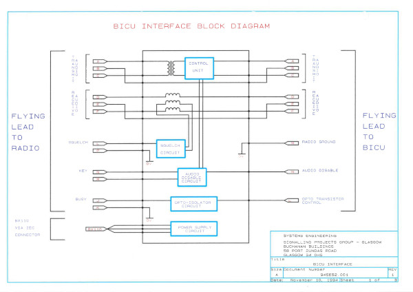
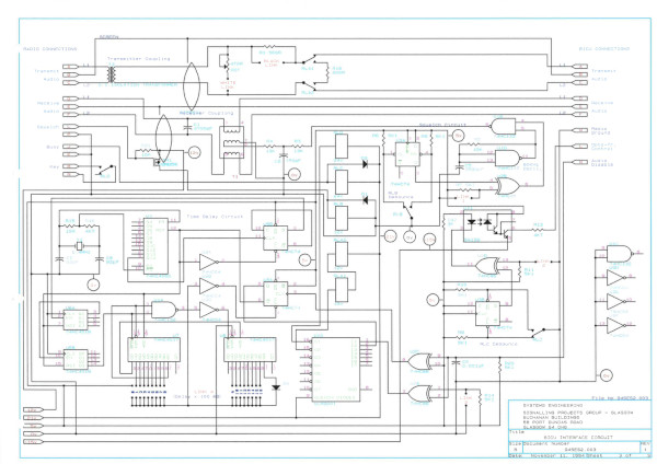 BICU, Block Instrument Control Unit, was a rebuild of a life expired radio interface used between Yoker/Craigendoran and Banavie. We reverse engineered the whole cubicle including PCB's and rebuilt it
as new. The cubicle was recently replaced with an NRS TDM.
BICU, Block Instrument Control Unit, was a rebuild of a life expired radio interface used between Yoker/Craigendoran and Banavie. We reverse engineered the whole cubicle including PCB's and rebuilt it
as new. The cubicle was recently replaced with an NRS TDM.