Systems Engineering Section Cards and PCB's
From 2005 we produced some of the simplest circuit boards ever made...
FE 05/022 Rev C - Axle Counter Restoration Relay/Module
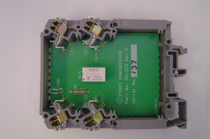
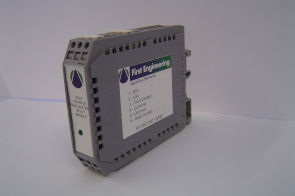
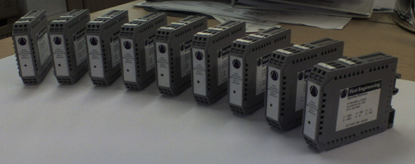
AzLM Axle Counters required a restoration relay which wasn't available in an easy to use package so we produced our own easy to wire module.
FE 06/001 Rev C - H/O/J Board
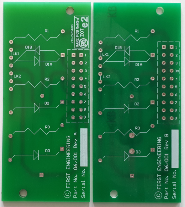
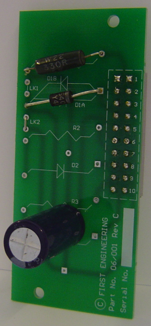
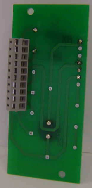
Capacitor, Resistor, Diode board, can accommodate 1 x HOJ or 3 x OJ. There were versions of this board, version A catered for axial capacitors, version B for both axial and single ended capacitors and version C added additional terminals to aid wire looping. The PCB is 3mm thick for rigidity.
FE 06/002 Rev A - J Board
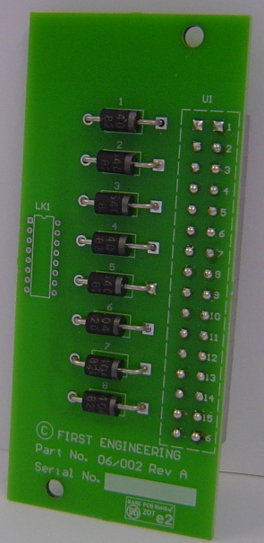
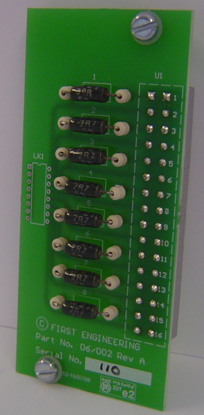
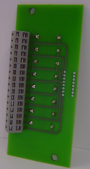
A Diode board but can accommodate various other components where required. The PCB is 3mm thick for rigidity.
FE 06/003 Rev C - AHBC Indication Control Unit
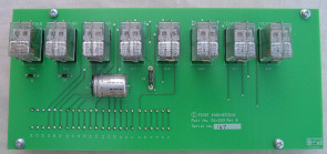
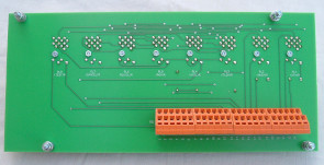
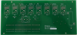
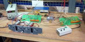
Level Crossing Typical Circuits (X08320) at this time describes the build of an AHBC Indication Unit which is normally contructed with relays and the associated inter-wiring. We simplfied this by using a circuit board to cut down the wiring to a minimum. Revision C allowed for Plug in capacitors and a higher wattage resistor.
FE 07/004 - Receiving/Transmitting Block Bell PCB3 & PCB4
To BRIS NW STD 017 Ver A and STD 018 Ver AFE 07/005 Rev B - Contstant Current Board PCB1
Built for Wigan Wallgate WWG/10/156.BAR 10/001 Rev A - Component Board
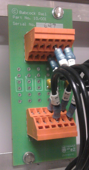
Generally used for up to 3 x VDR's or 6 x miscellaneous components.
BAR 11/001 - Blank board
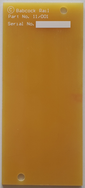
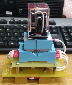
A popular board for mounting various switches/buttons in a standard relay space. The example here shows a non-standard mounting relay converted to a standard relay base fitting.
BAR 11/002 Rev A - Audible Warning Limiter
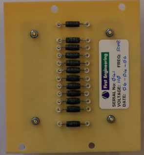
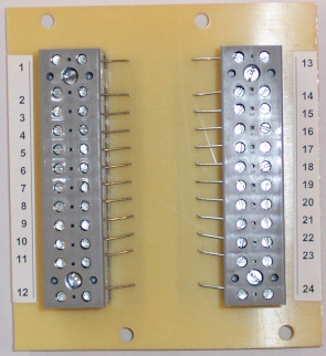
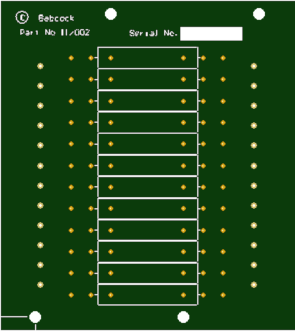
MCB Typical Circuits X00180/X00181/X00182, MCL X60300/X60301, ABCL X20170/X20180 describes a resister ladder for selecting suitable attenuation for limiting the volume of the audible warning sounder. This was normally built using strip, tag board or as above so we produced a two relay space PCB giving a professional product. Unfortunately I don't have the photo of the board but the above is the Gerber view.
BAR 12/001 - HOJ Board
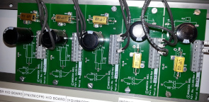
Capacitor, Resistor, Diode board, can accommodate 1 x HOJ in many configurations - more versatile than FE06-001. Also designed for high wattage resistors.