Practical Electronics RP2350B Computer
I have bought and built projects from the Practical Electronics Magazine many times over the years, I still have the odd copy from 1974! but the latest magazine caught my eye with the publication of a very well specified RP2350B computer. Reading the article got me thinking about building it myself, all the information is there including the Gerber files for the PCB.
When I got home I downloaded the Gerbers and uploaded them to JLCPCB, sorted out a couple of 'out of stock' parts and got a quote for the assembly. Minimum order was 5 PCB's with 2 assembled. Comparing the cost to buying them directly through the magazine and buying such a small quantity from JLCPCB it turns out that JLCPCB is the expensive way to get hold of them. I opted to buy from the magazine but this involves a delay in despatch as it put my order on 'back order'. I guess they are building up a sensible order quantity before they order themselves from JLCPCB. So it's a waiting game..
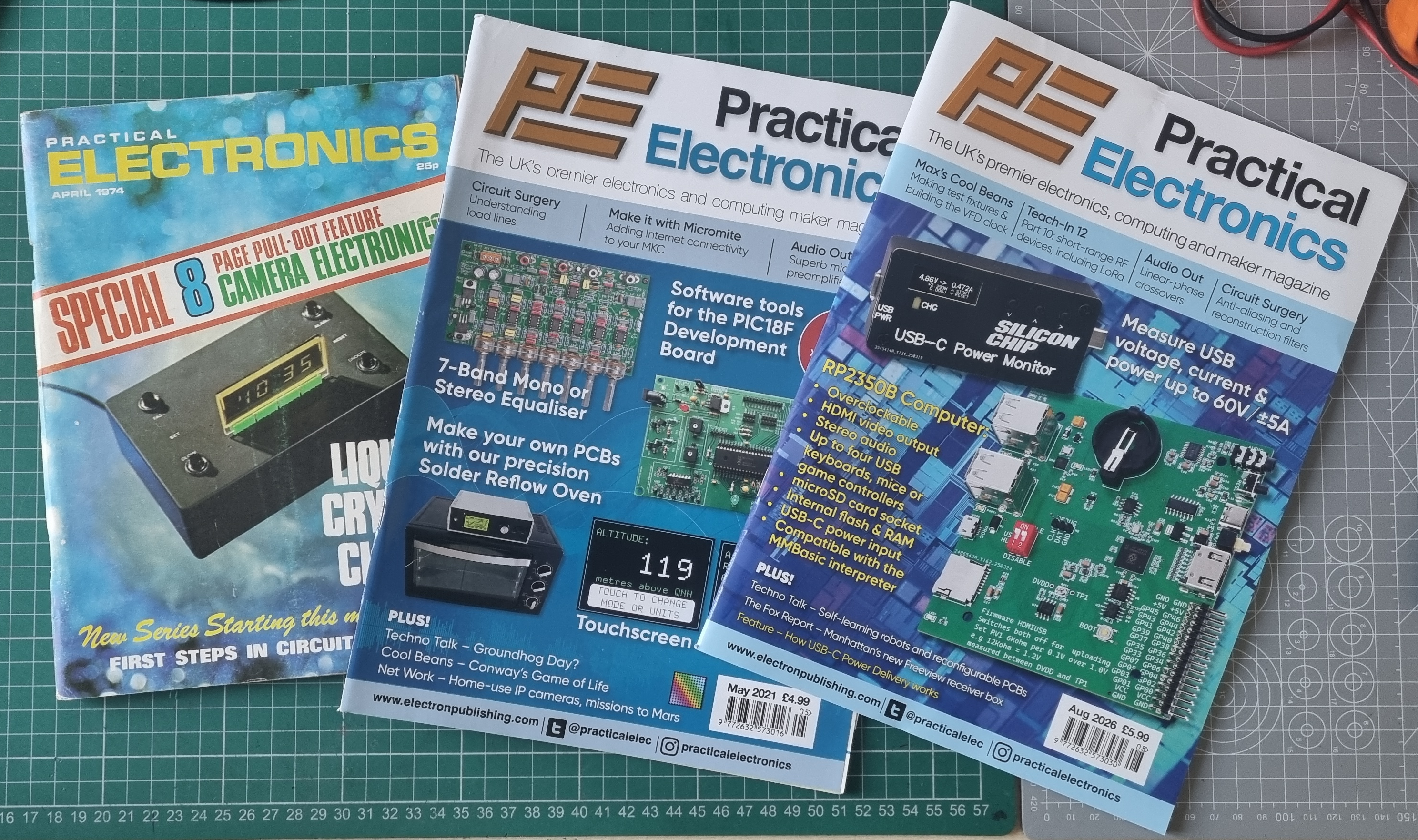
PE through time with a copy from 1974 and the latest showing a well spec'ed Pico computer.
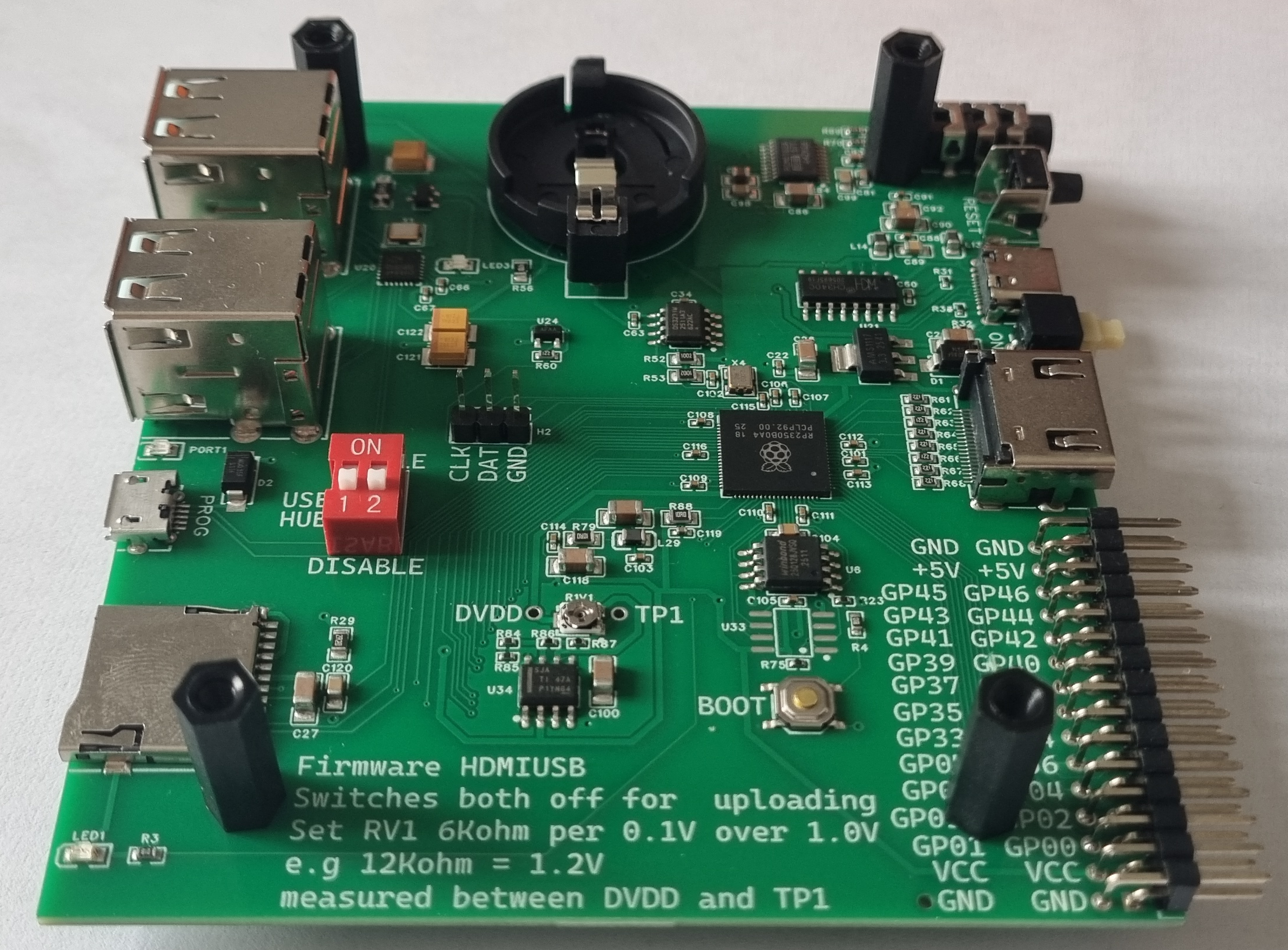
It didn't too long for the boards to arrive, I unpacked one and it looks good. The boards measure close to 100mm x 95mm, slightly bigger if you take the overhang of components into account.
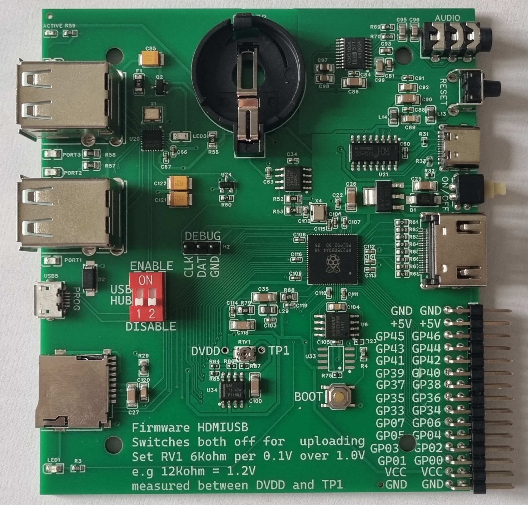
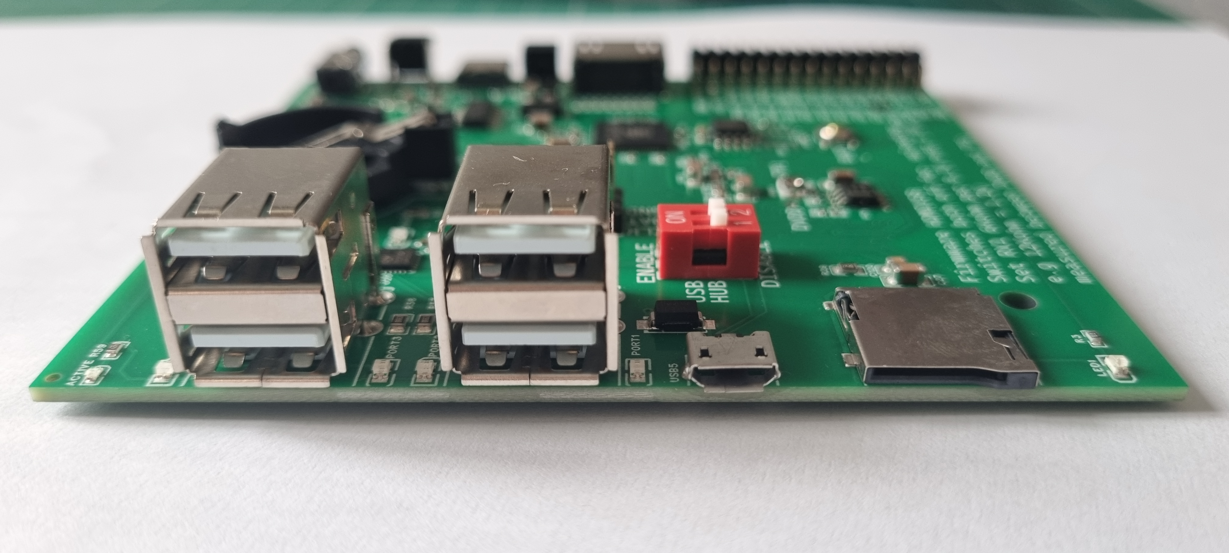
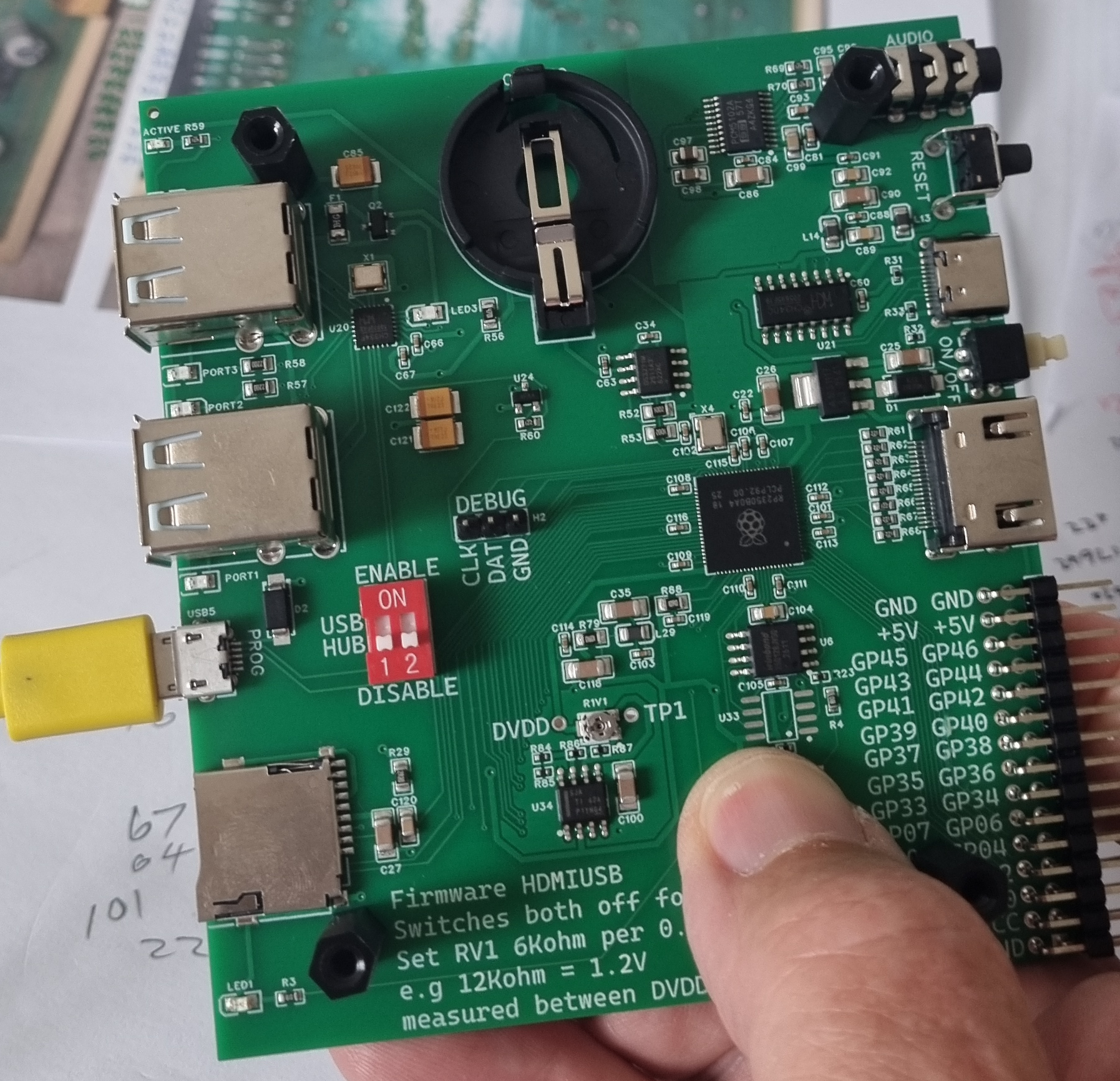
Two edges have connectors running along them. The left had edge has (from left to right) 4 x USB2 sockets, a Micro USB and an SD card socket.
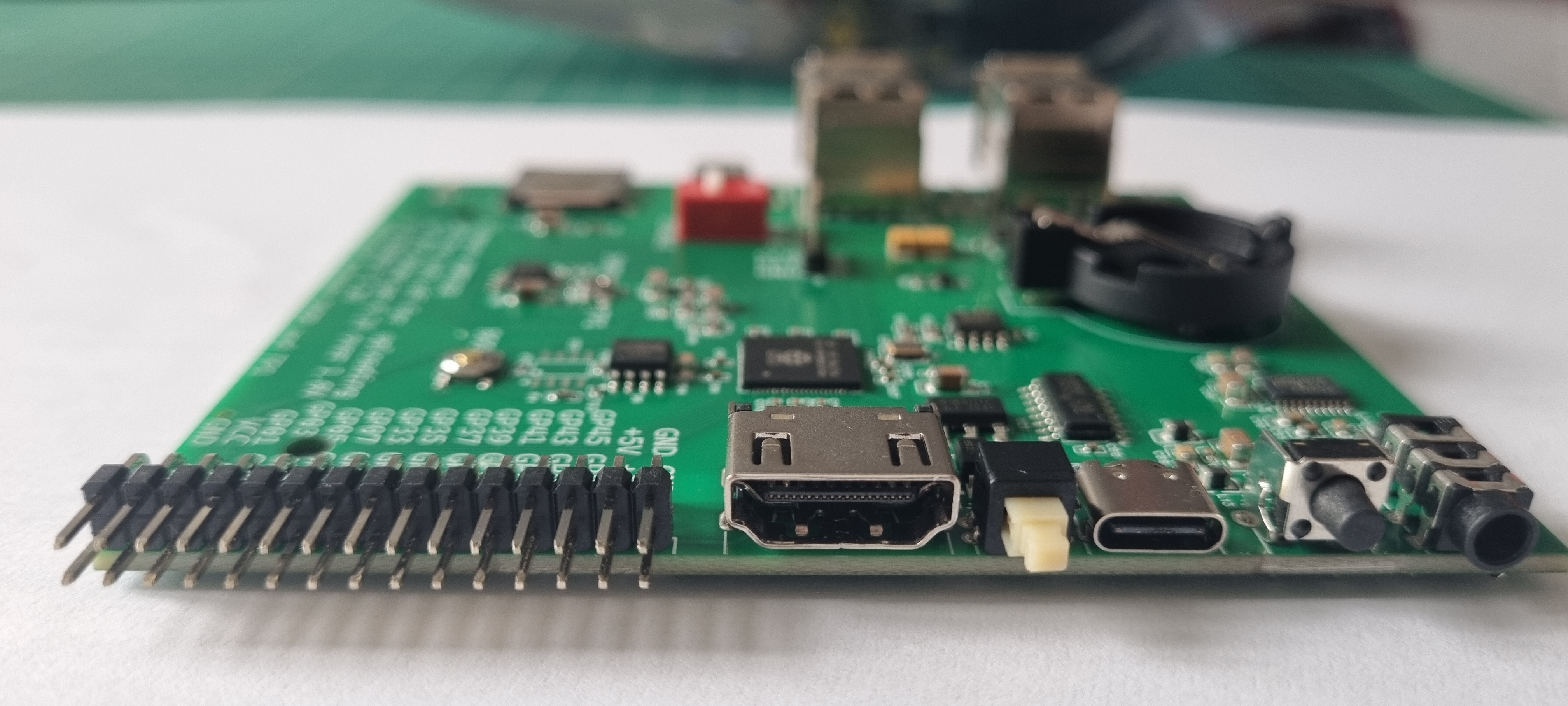
On the right hand side a 2 x 15 way header with 22 GPIO, Ground, 5V and 3.3V connections, a full size HDMI socket, an ON/OFF switch, a USB C connector (power), a Reset button and an Audio jack.
There is also an on board battery holder for the RTC.
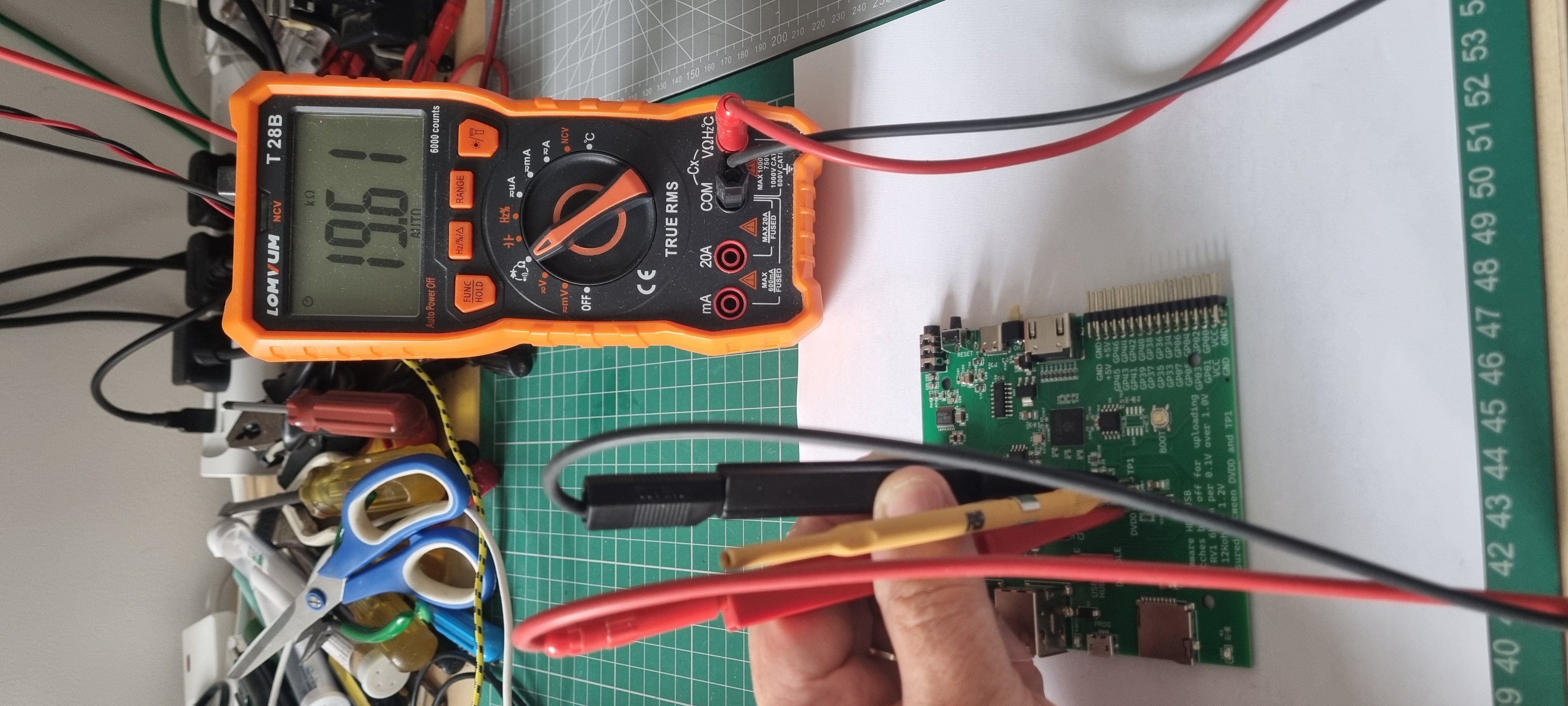
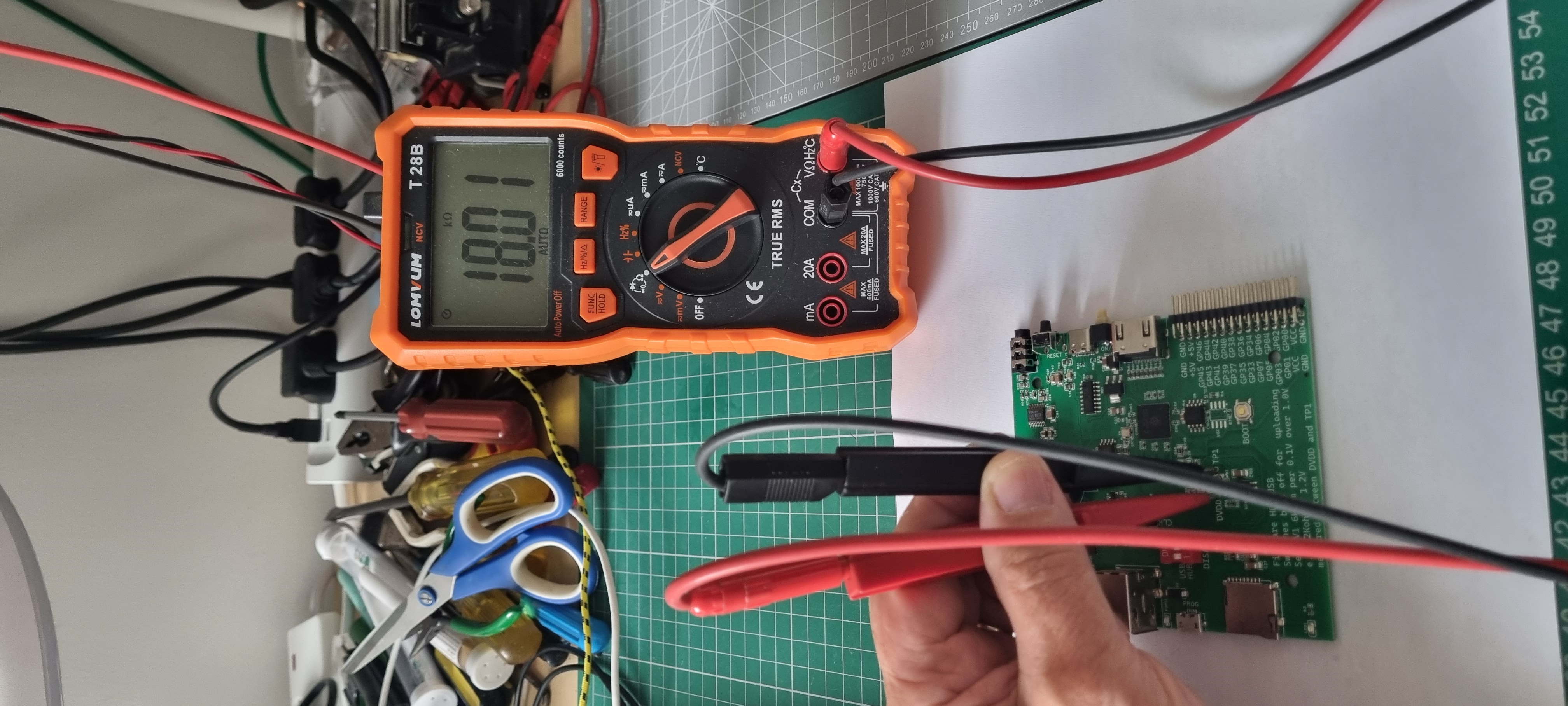
The magazine gives a good guide to setting up the board for the first time. The first thing that needs to be done before power on is to set up the CPU voltage and the way this is done is to measure and adjust the resistance between two test points. Mine arrived with the measured resistance of 19K ohm, setting it to 18K should provide a voltage of 1.3V which is required as the CPU is over clocked to achieve the higher resolution HDMI output.
I also added some pillars above and below the board so it'll be safe from shorts when left on the bench.
With that done it is safe to power up for the first time. The process of installing the firmware is almost the same as the RP Pico but first disable the USB hub with the on-board switches then press and hold the boot button down and power on via the Micro USB cable which should be connected to your PC.
The magazine gives the web address for the firmware download so just unzip that and drag and drop it onto the drive that appreared when powering on. I used the PicoMiteHDMIUSBV6.00.03.uf2 as this version supports the on board hardware.

Once that process is complete the drive window will disappear and it can be unpluged. The next step of the process is to swap the Micro USB cable for a USB C one and plug it into the USB C socket on the board.

For the next part of the process I needed a comms program such as PuTTY and set it up to communicate with the board. First I had to find the boards COM channel which can be found in the Windows device driver window, in may case COM3 and set the speed to 115,200. Next I opened PuTTY and set that to the same settings and hit connect. That gave me the connection to set up the USB and HDMI ports.
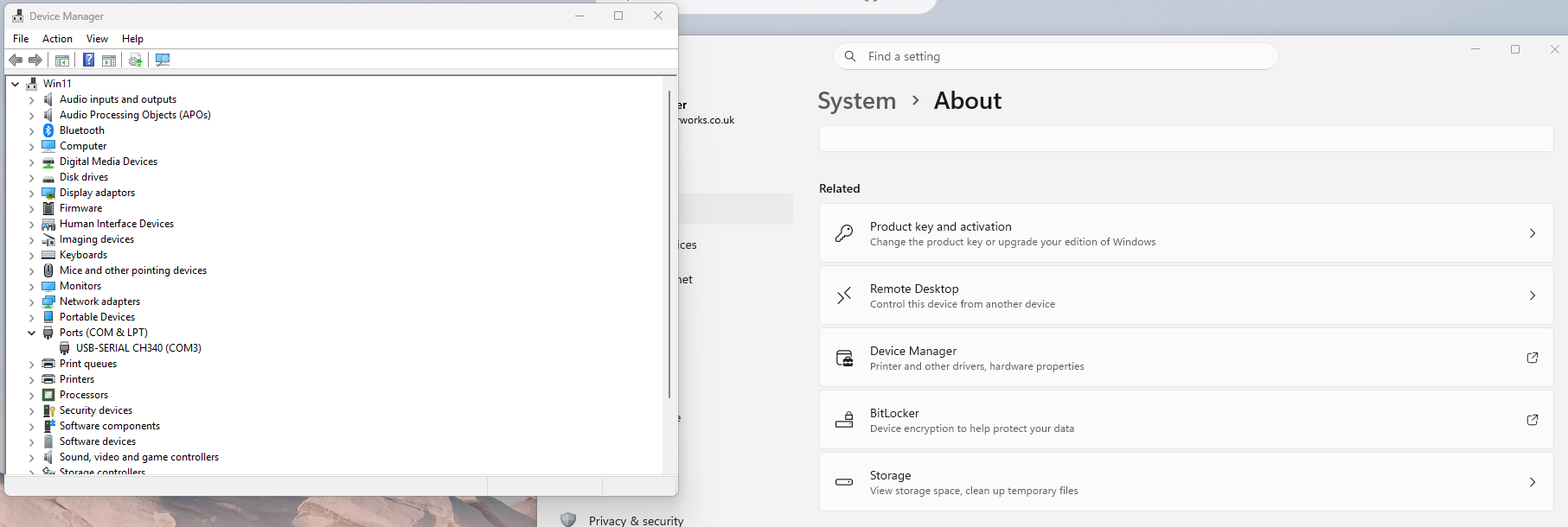
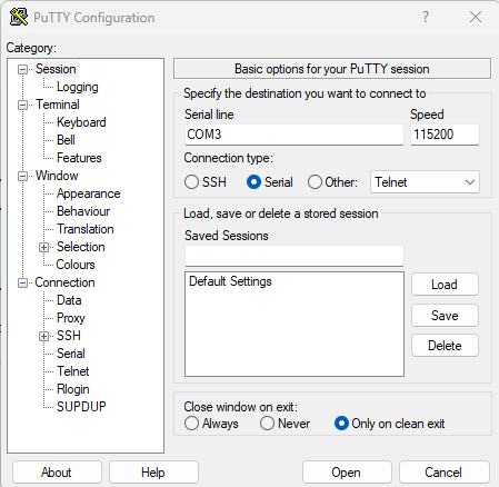
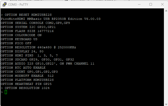
Setting up the USB and HDMI ports and setting the resolution.
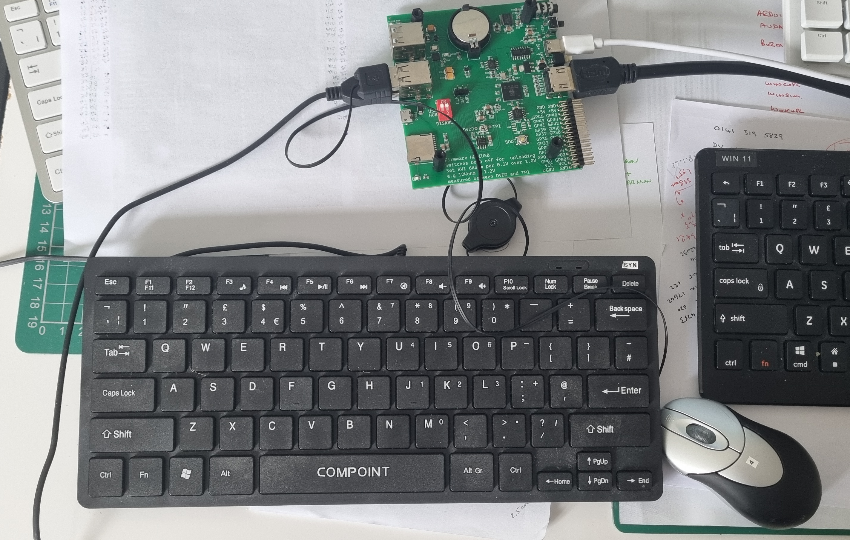
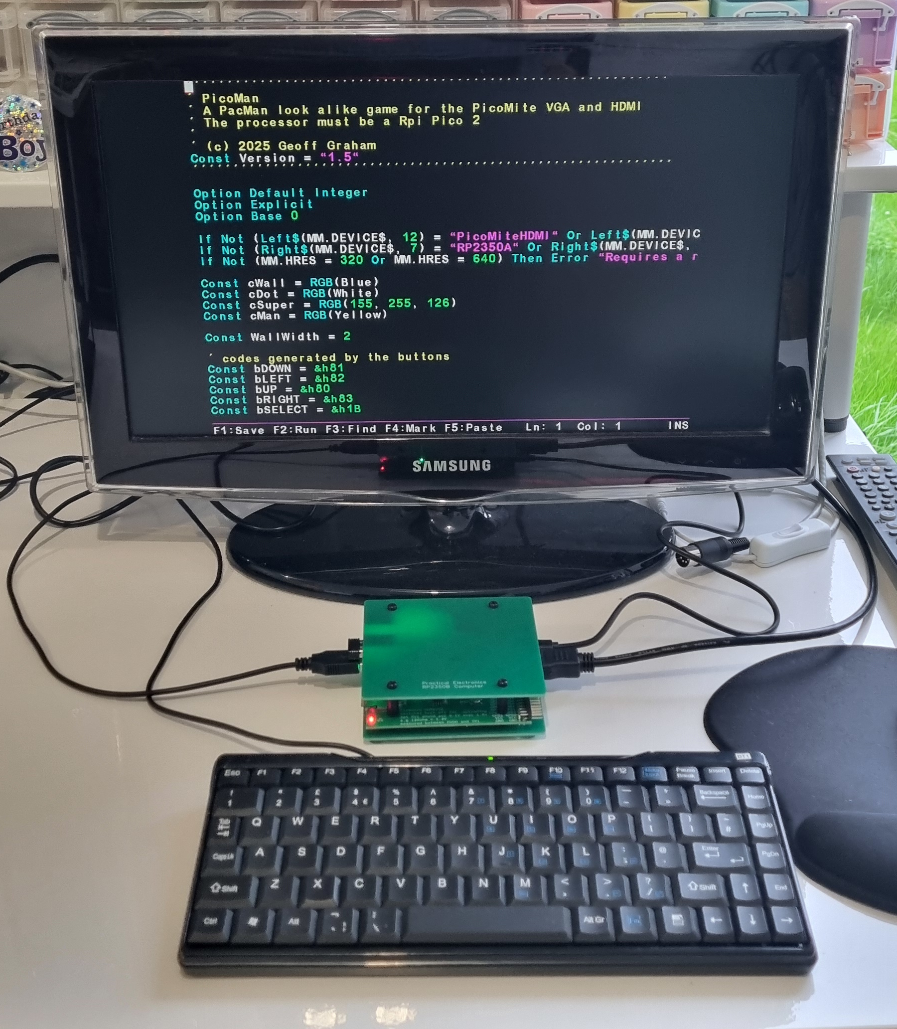
That's basically it - I unplugged it, added the battery for the RTC, plugged in a keyboard and mouse and a monitor and switched it back on.
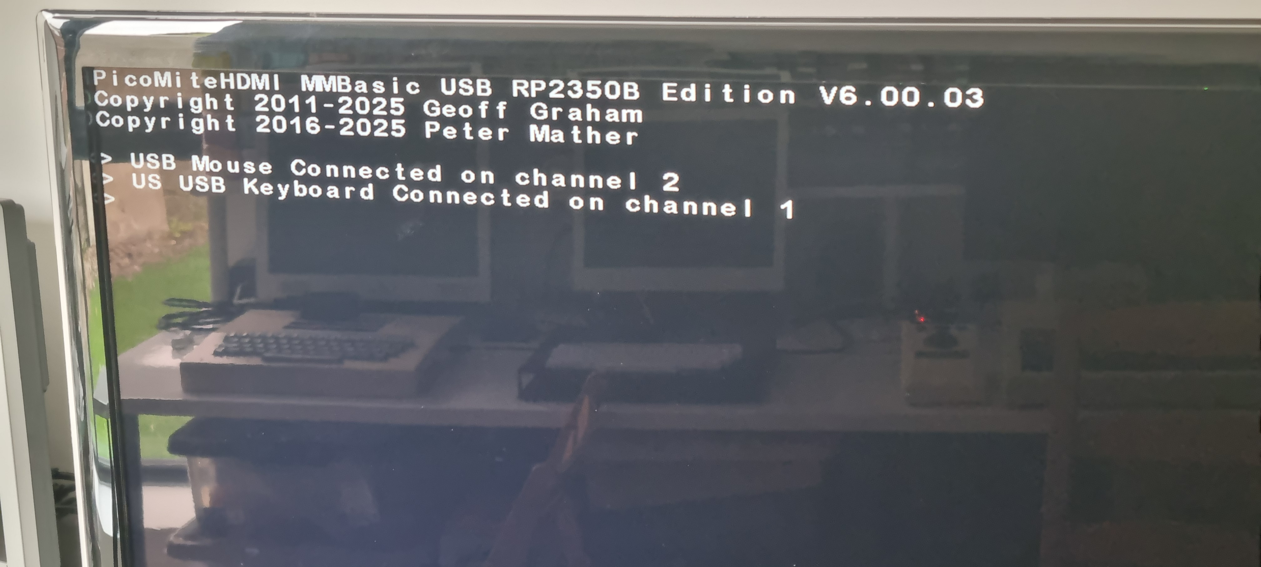
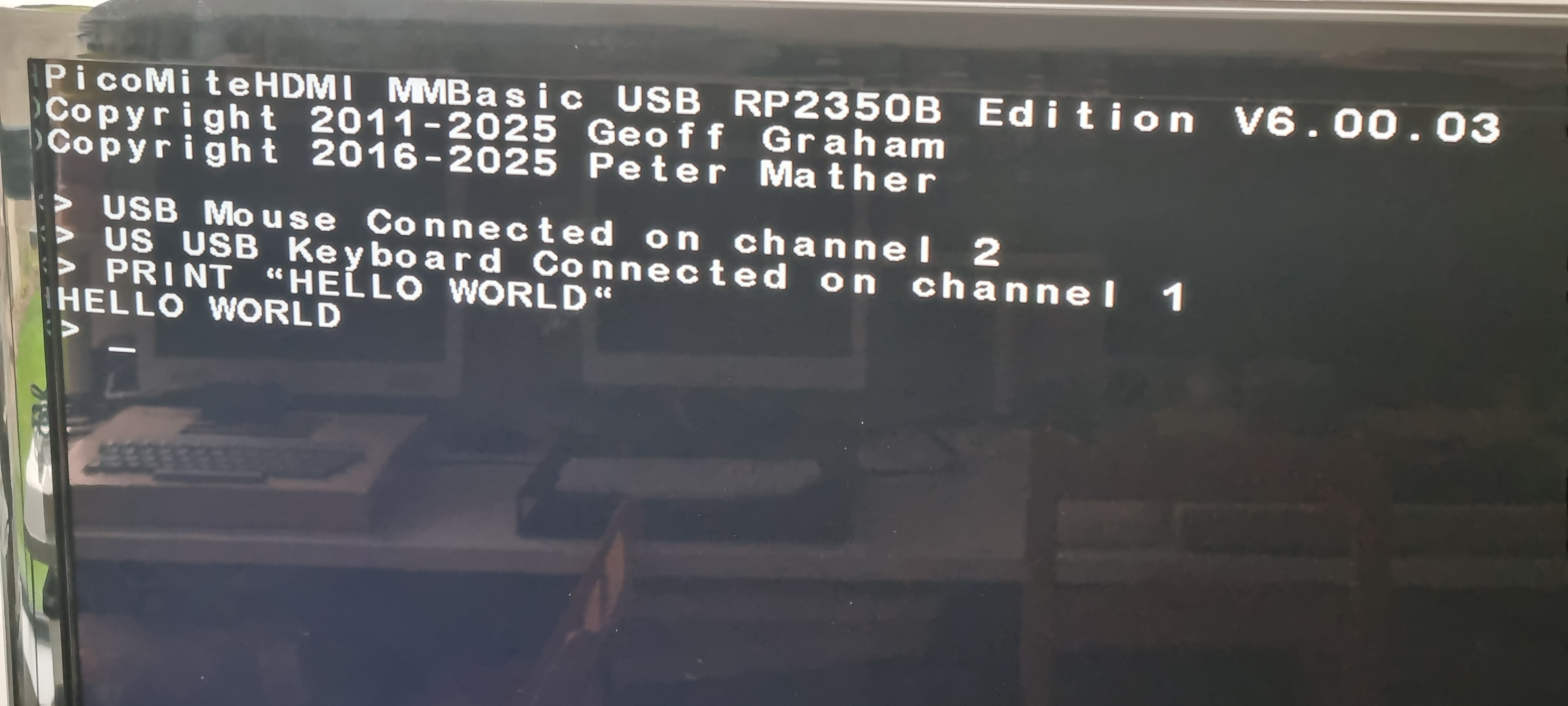
It's always good to see it work first time... and I couldn't resist a 'Hello World'
I thought I'd do something slightly fancier so I opened the editor and wrote a simple loop to line up the text when scolling.
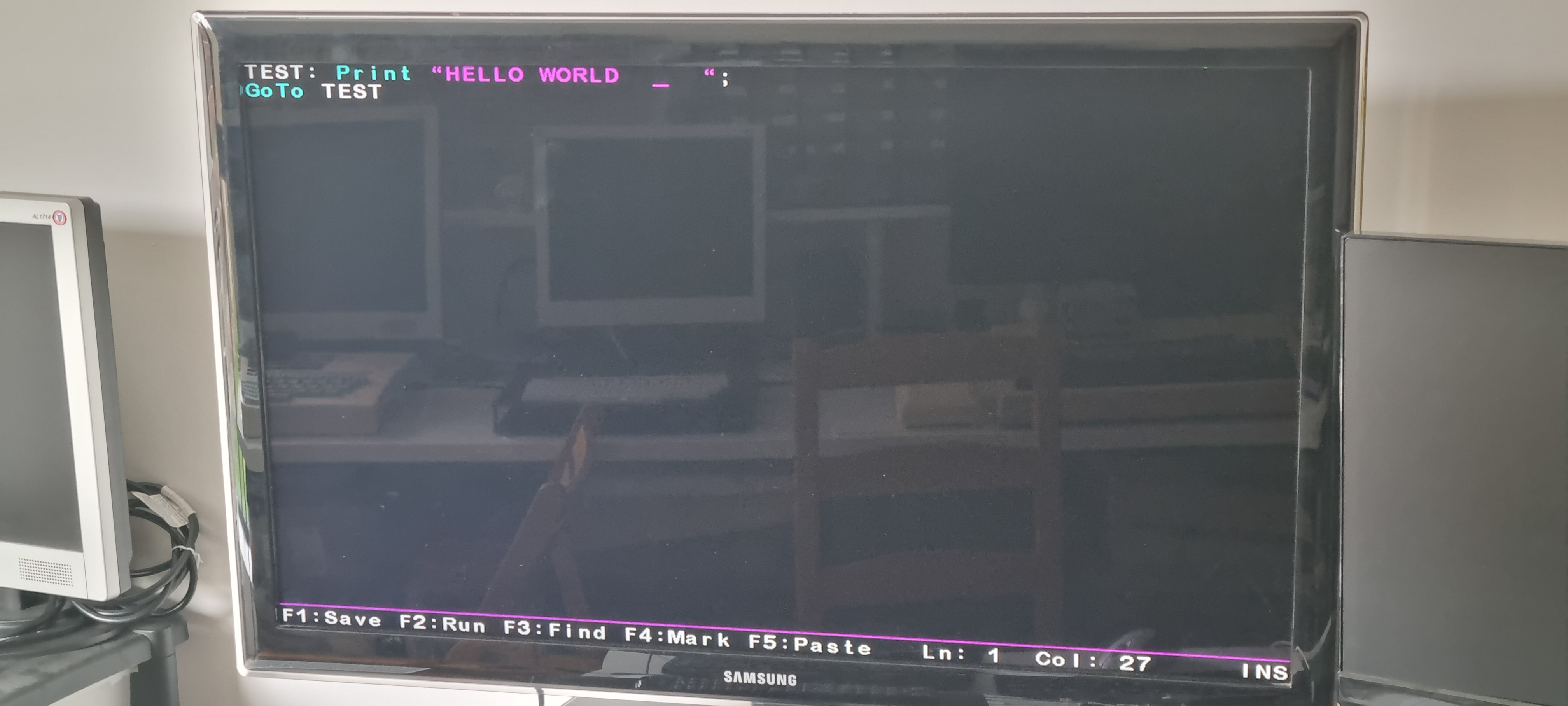
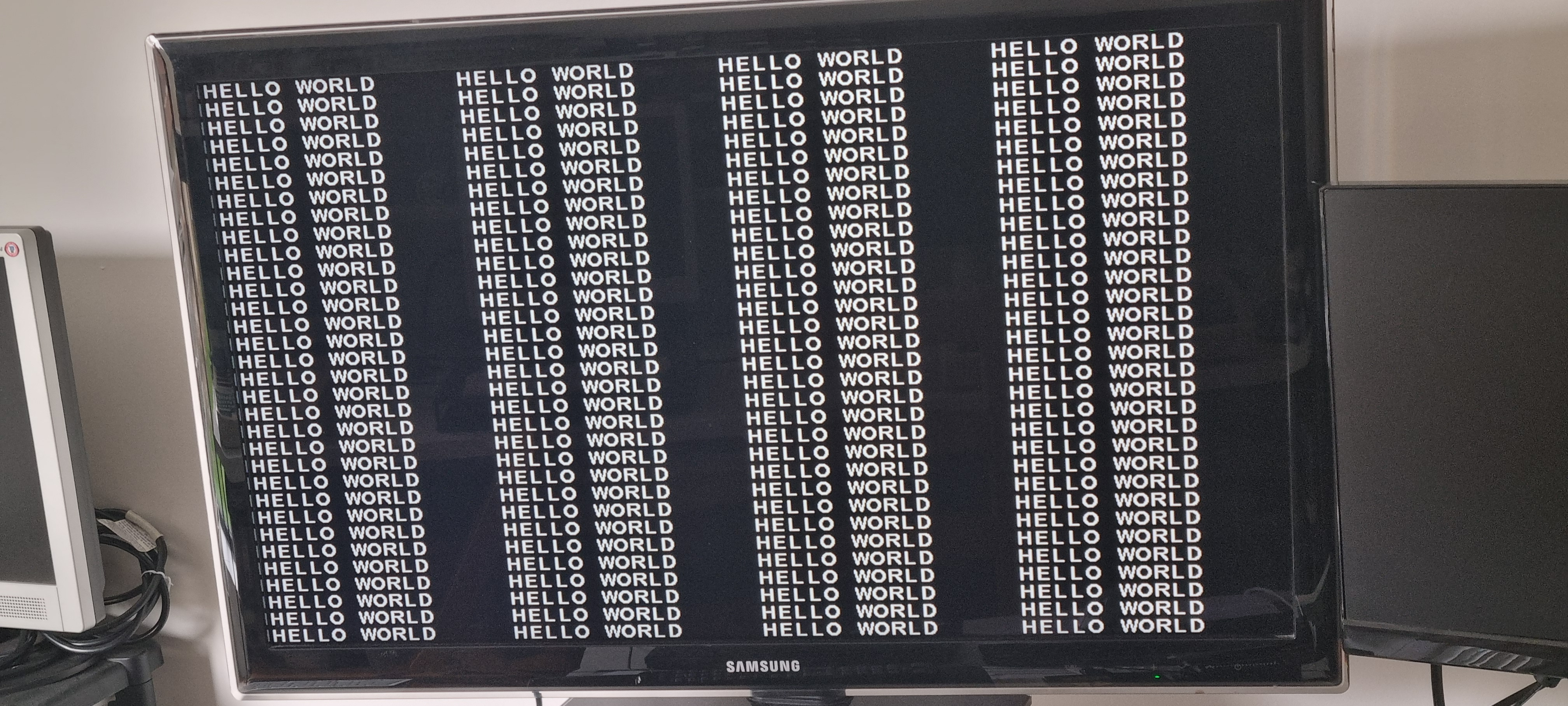
That's it for now, I have a lot of learning to do for example how to read files from the SD card! and how Basic handles the GPIO..it'll keep be busy for a while.
Two wee niggles so far, the keyboard is detected as US and not UK (some characters assigned to different keys) and it powers up with Num lock on! That gives me something to look at first.
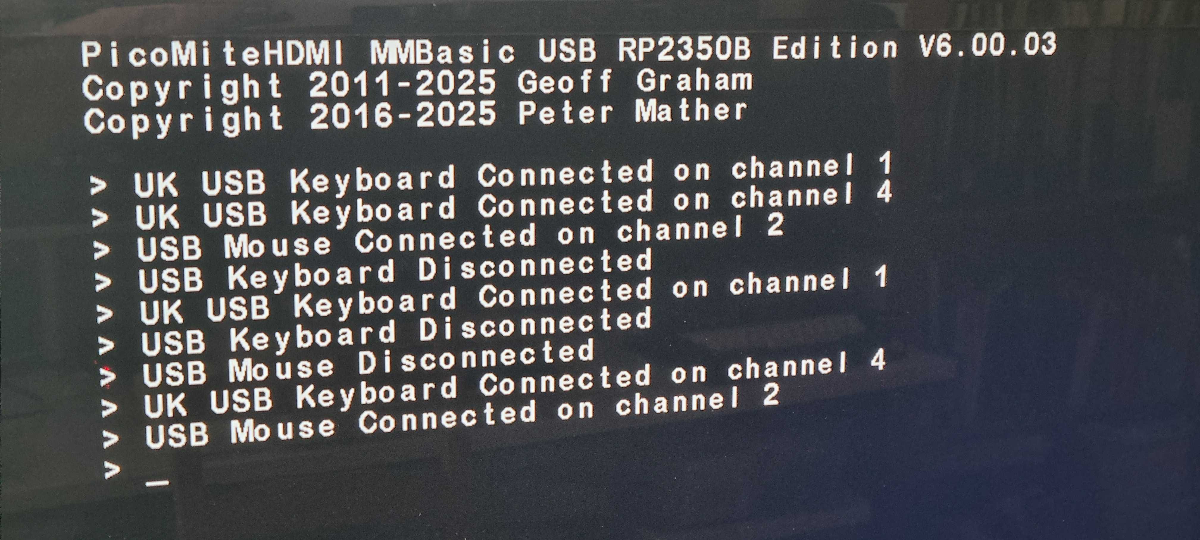
Easily sorted! I used OPTION KEYBOARD UK,0,0 - This switches the keyboard to UK with Caps and Number Lock off. If you want Caps Lock ON and Num Lock OFF the command is: OPTION KEYBOARD UK,1,0
Still on the subject of the keyboard, when I plugged in my wireless USB mouse it took up two channels - a keyboard, channel 4 and a mouse, channel 2. Is this normal behavour for a wireless mouse? It's not problem as the mouse works perfectly, just some to look into.
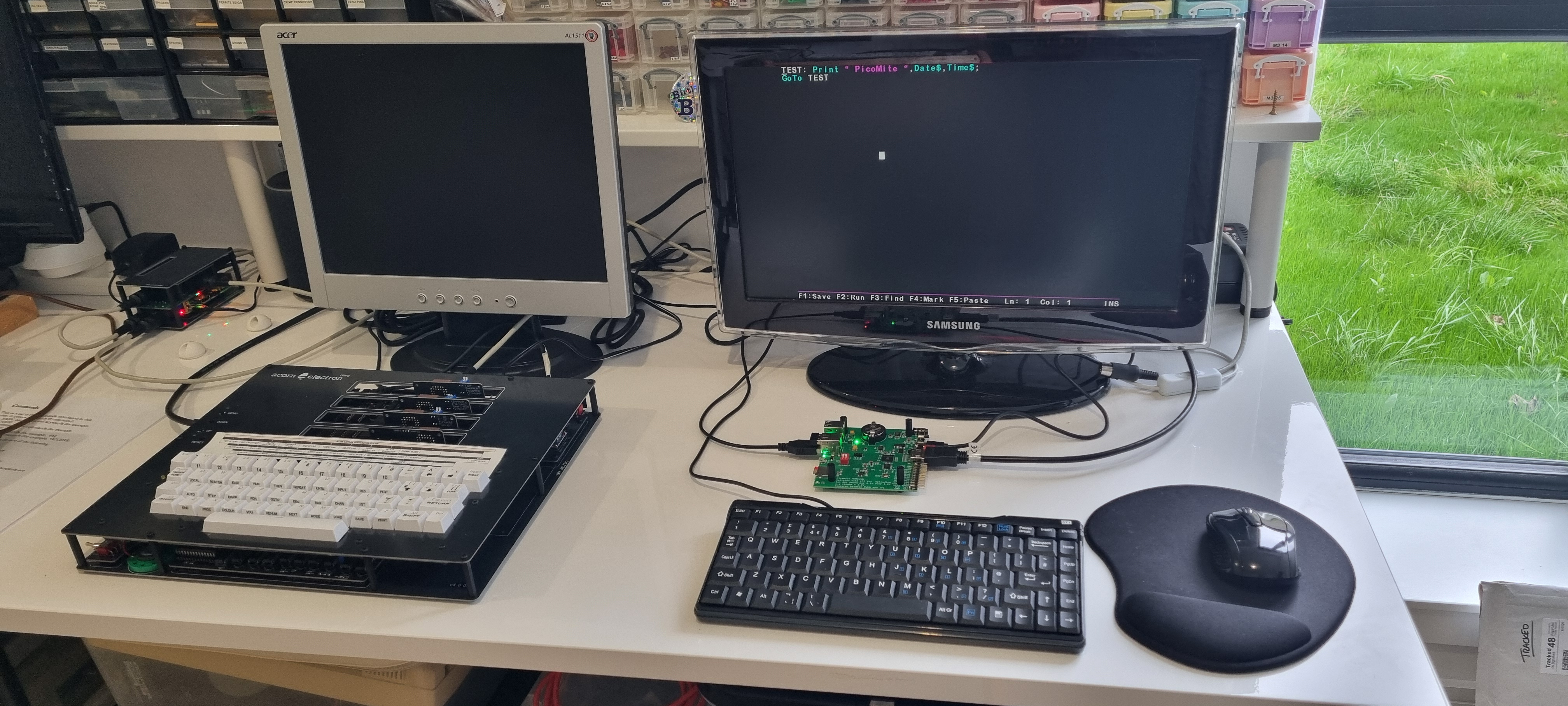
I gave the little computer a home for itself next to my Electron Ultra and I've ordered a top & base case for it.
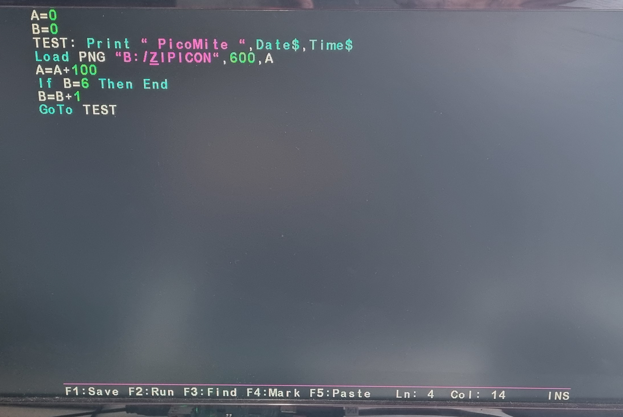
Starting to play with it a little to get the feel of how MMBasic works. Being used to BBC Basic it shouldn't take long to find the basic differences.. no COPY key but it does store line history so that's ok and I want to type L. to list a program but that doesn't work.. lots of small differences. I'm used to using BASIC Editor on the Electron so having a good Basic Editor is great - colours..so much clearer.
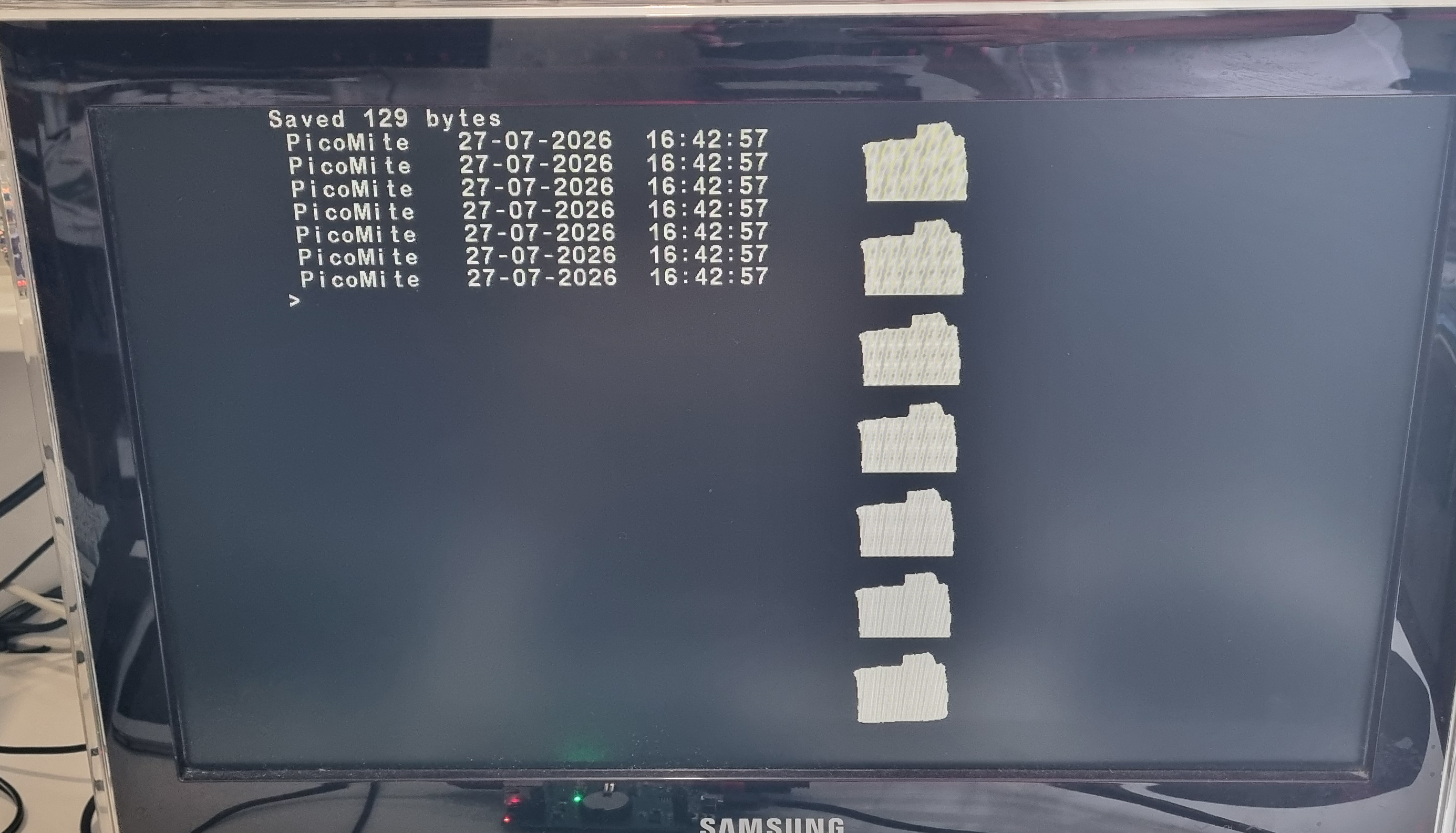
The results of the above program, print text and a PNG file to the screen - screen is in two colour mode, still to try colour modes.
Something to protect the PCB - The Practical Electronics magazine gives details of a case and they also provide Gerber files for the front and back panels but I wanted to keep the style the same as my Electron Ultra and Pi5 so I made a panel that fits top and bottom to protect the circuit board. I kept it green to match the circuit board and to make it visually different from the Pi5 case.
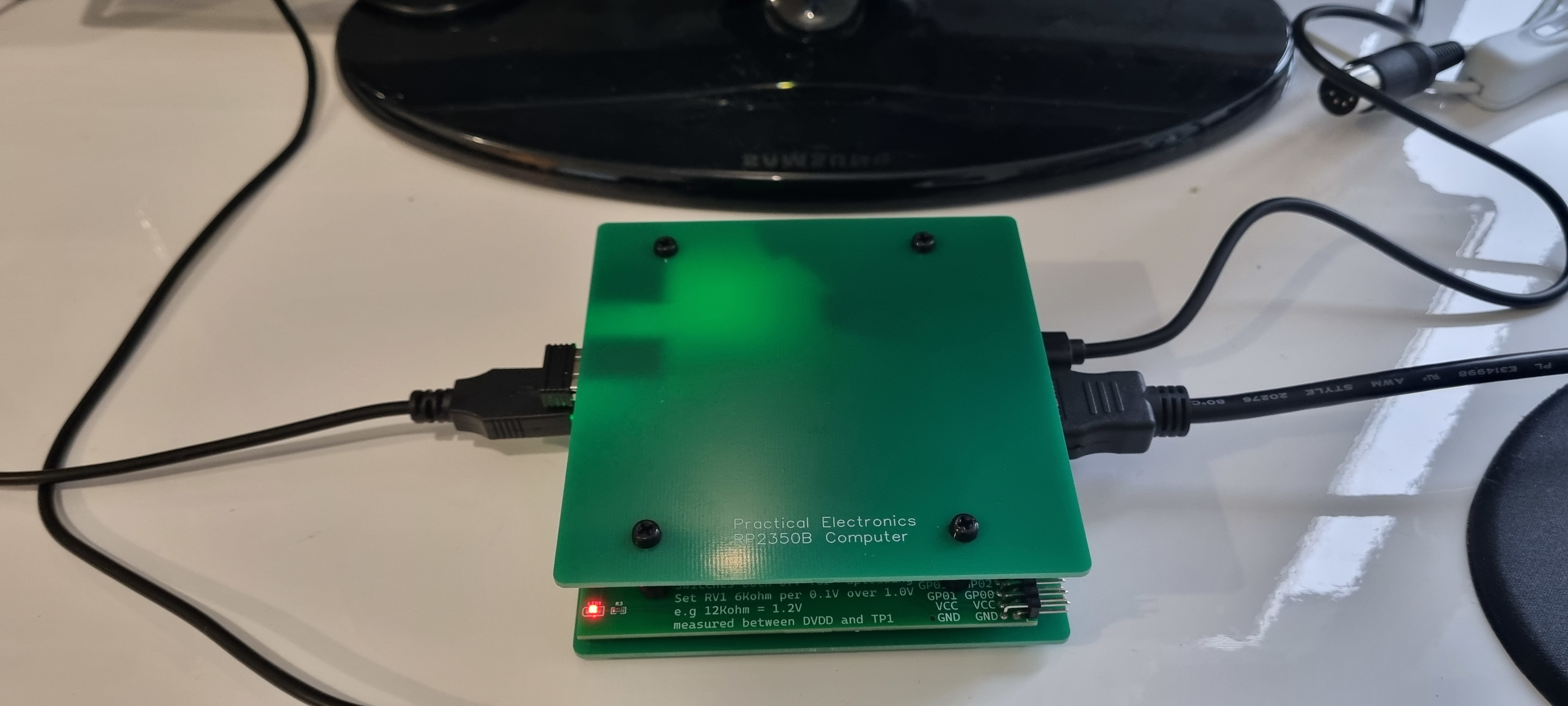
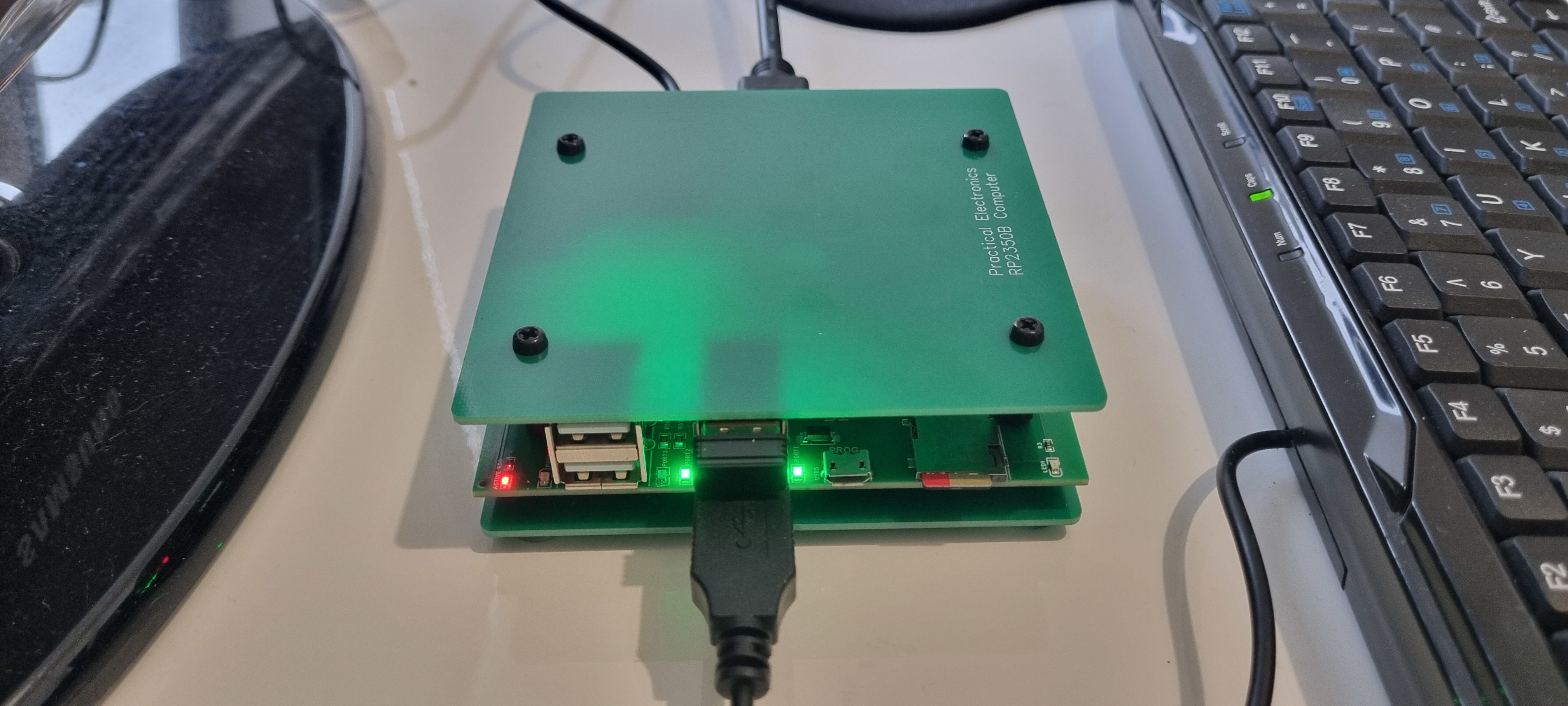
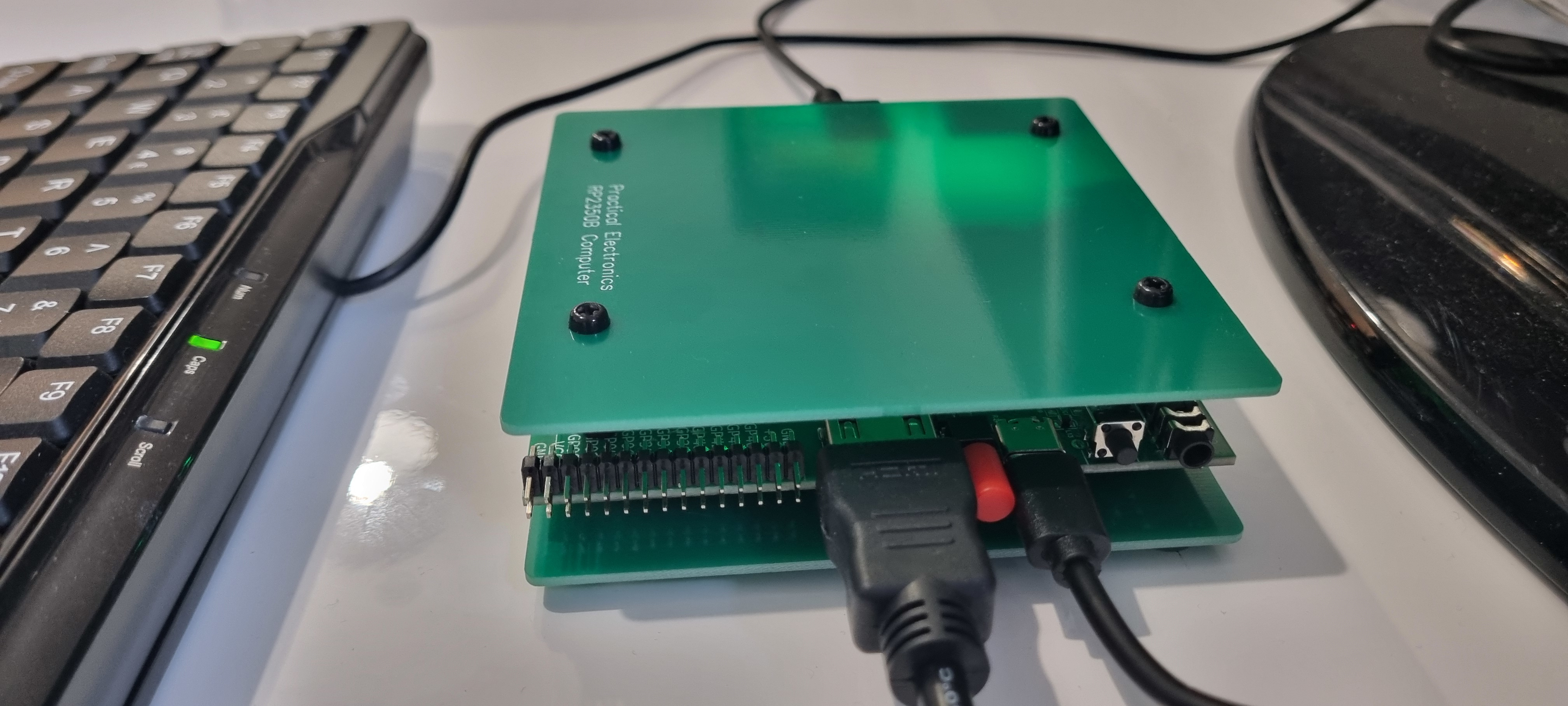
To make it easier to switch on/off I fitted a red cap on the switch, this highlighted how close all the edge connectors and switches are. I shaved off a few millimetres of the HDMI connector grip to allow free movement of the switch. Works great now.
At this point I thought I'd try out the two games that came with the firmware, PicoMan and Blocks. Both are very playable games but for some reason the HDMI screen resolution of 640 x 480 doesn't fit my screen...
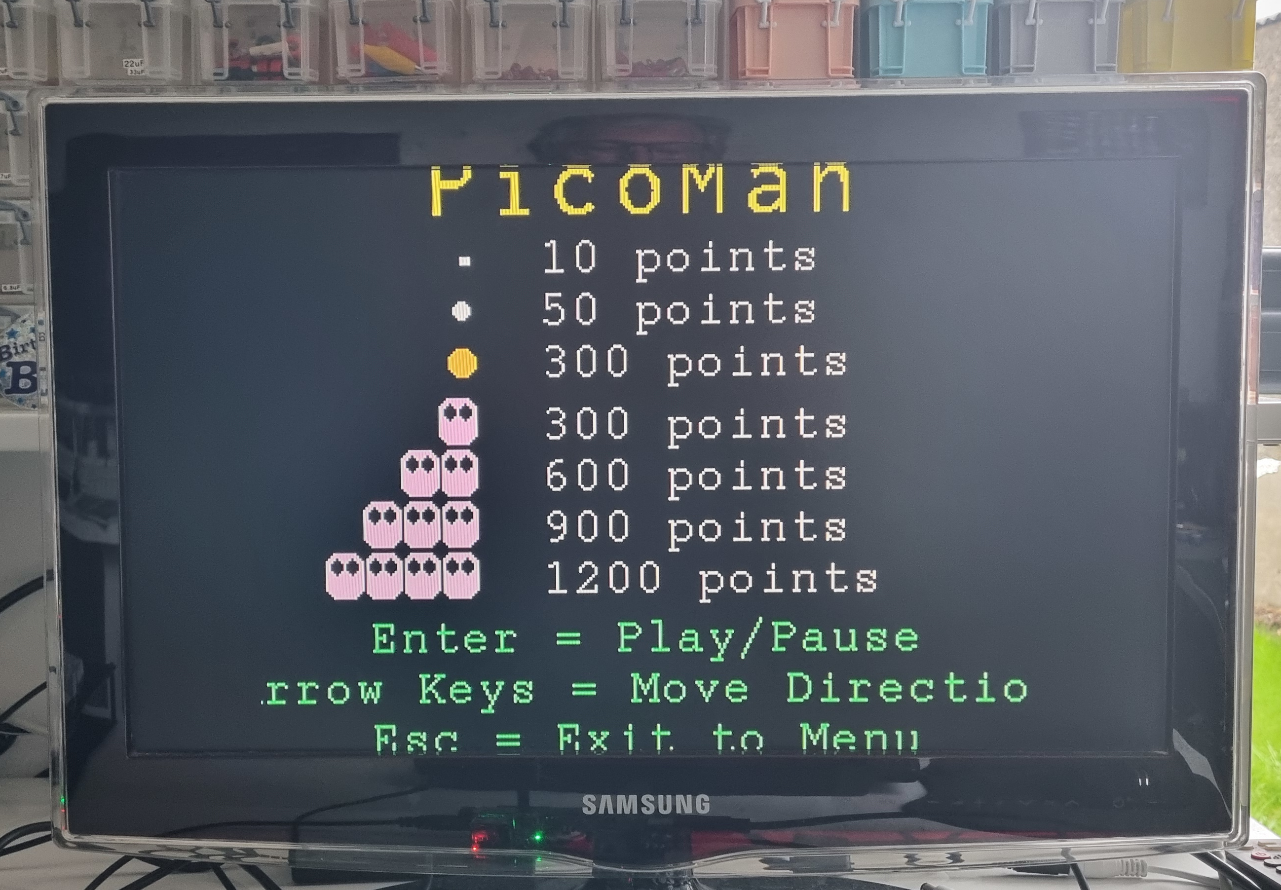
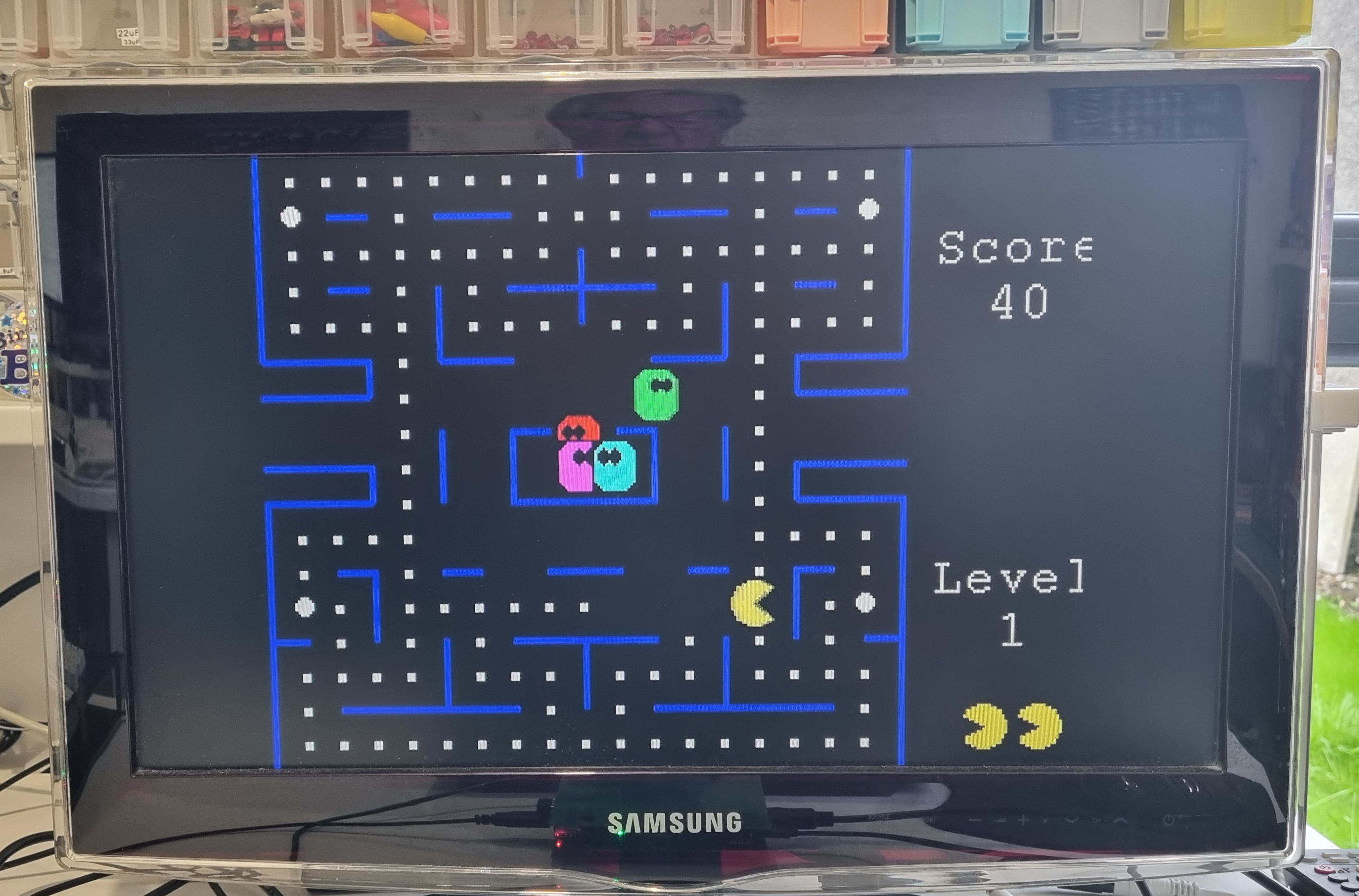
Something else to learn about..
Interestingly the manual discusses how to use from BASIC some of modules that I've used on the Pico in the past. Modules such as the DS18B20 for temperature measurment, the DHT22 humitity and temperature measurement, LCD displays up to 4 line and so on. I'm tempted to try out one ot two of these to see how easy it to program.