RGBtoHDMI adapter
I was looking for something to do while waiting on some circuit boards to arrive for a future project when I came accross a bag with left over components from an earlier build of RGBtoHDMI adapters. These adapters were used in my clone Electron and a couple free standing units for my other Acorn machines.
I had enough parts to built two more and I see I haven't document any of the builds so perfect for another web page.
This time I'll build and install one in my clone v1.1, the one where I first added Mode 7 and the other will be kept as a spare.
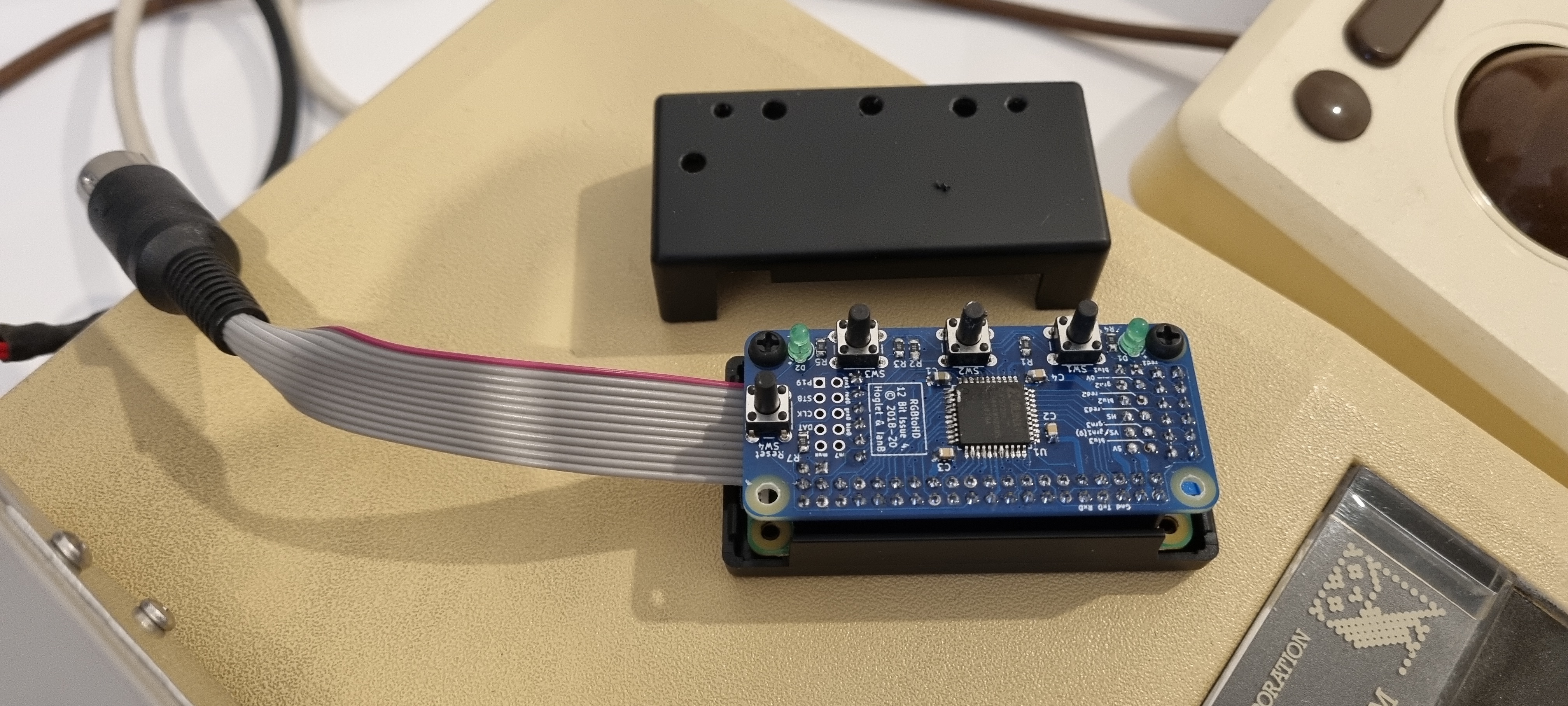
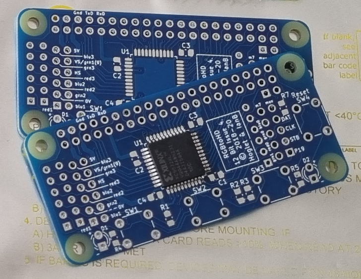
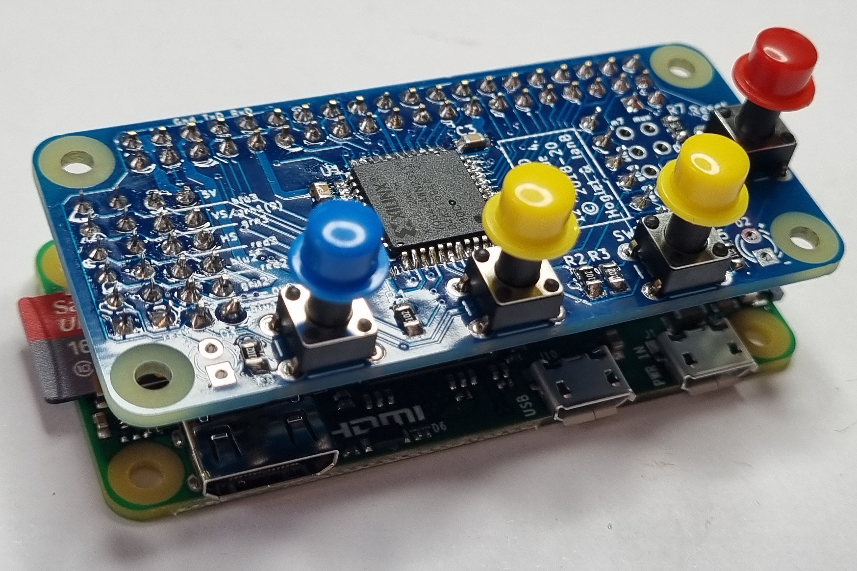
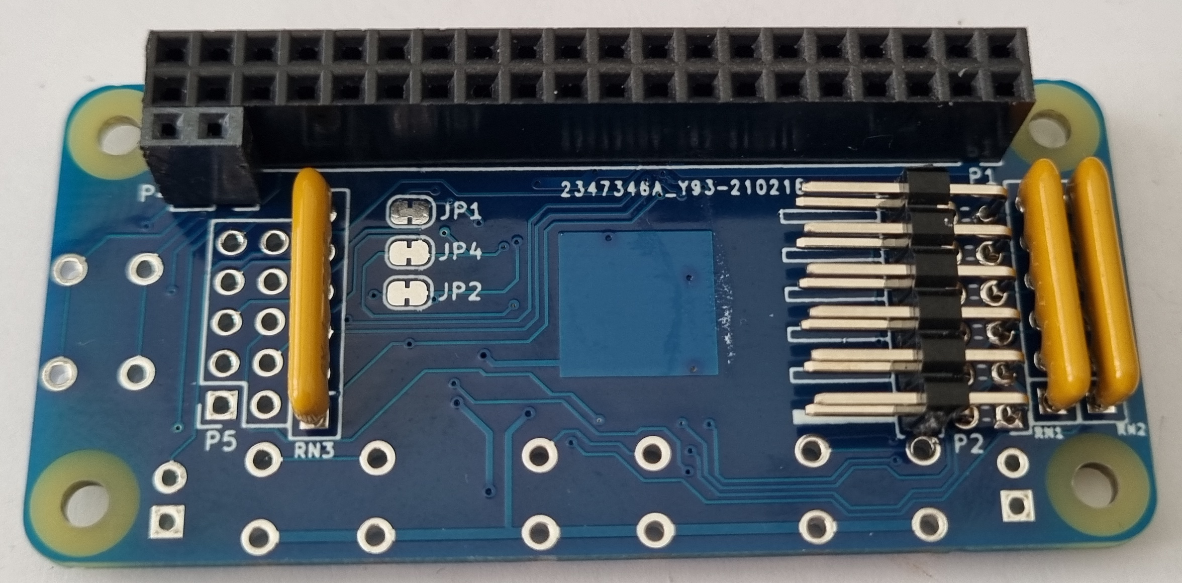
The first item to solder on the boards is the Xilinx chip then the other surface mount components, resistors and capacitors. After that I soldered the three SIL resistors and the headers. I use a very fine tipped soldering iron and a good magnifying light to see and solder the surface mount components.
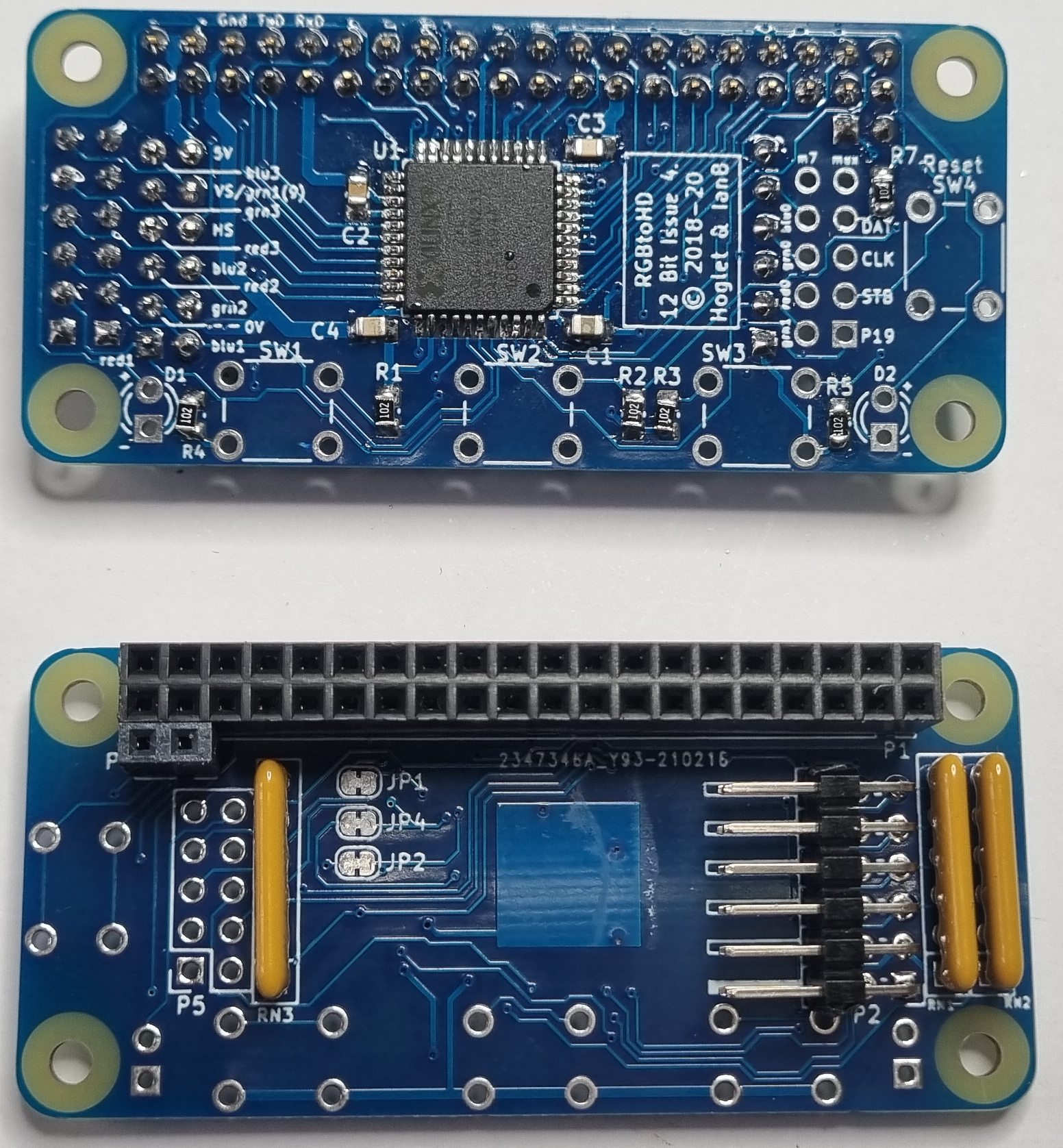
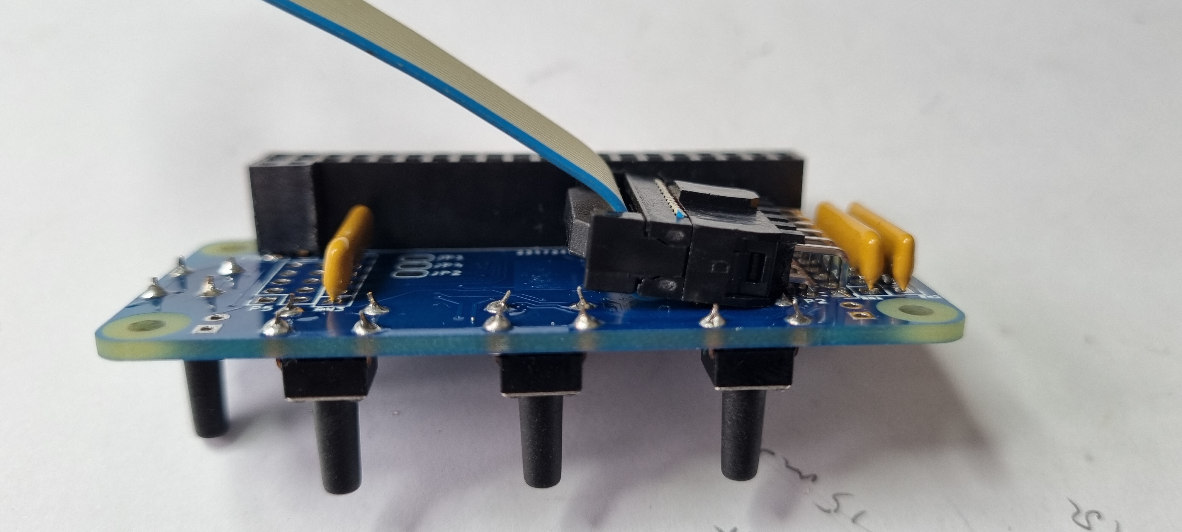
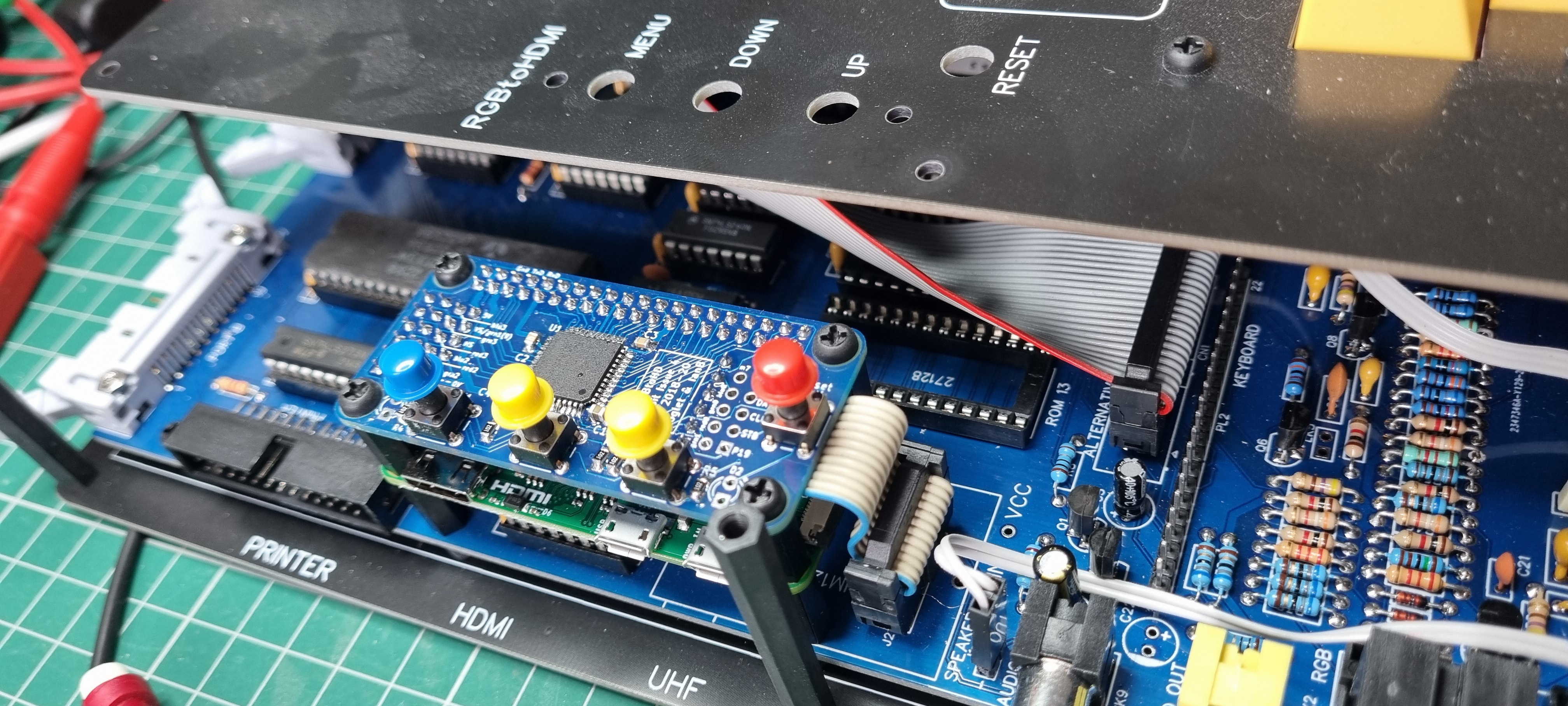
I fitted the 2x6 way header with a slight angle to allow for the ribbon cable and the keyswitch solder pad. A later photo will show this a bit clearer.
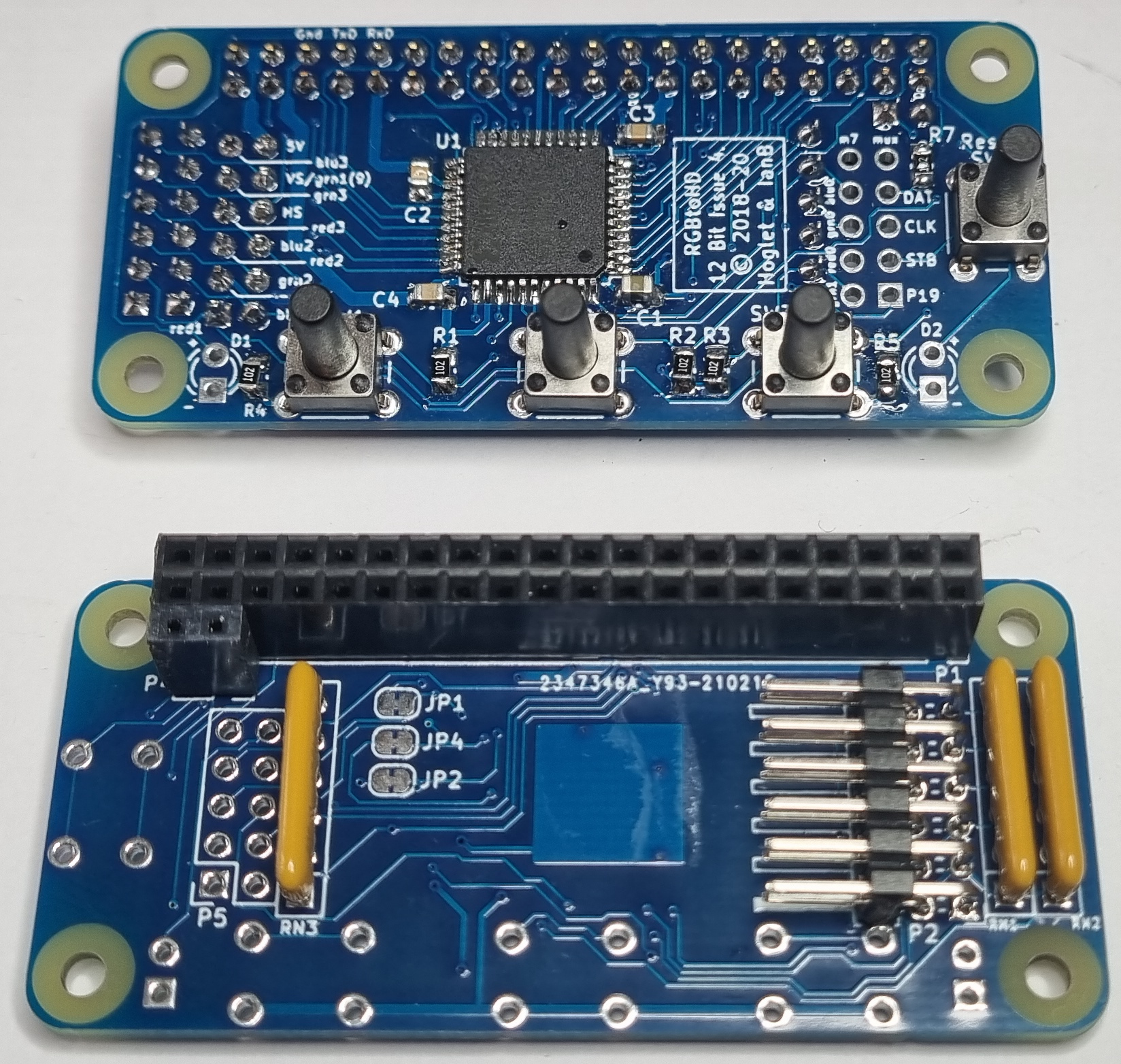
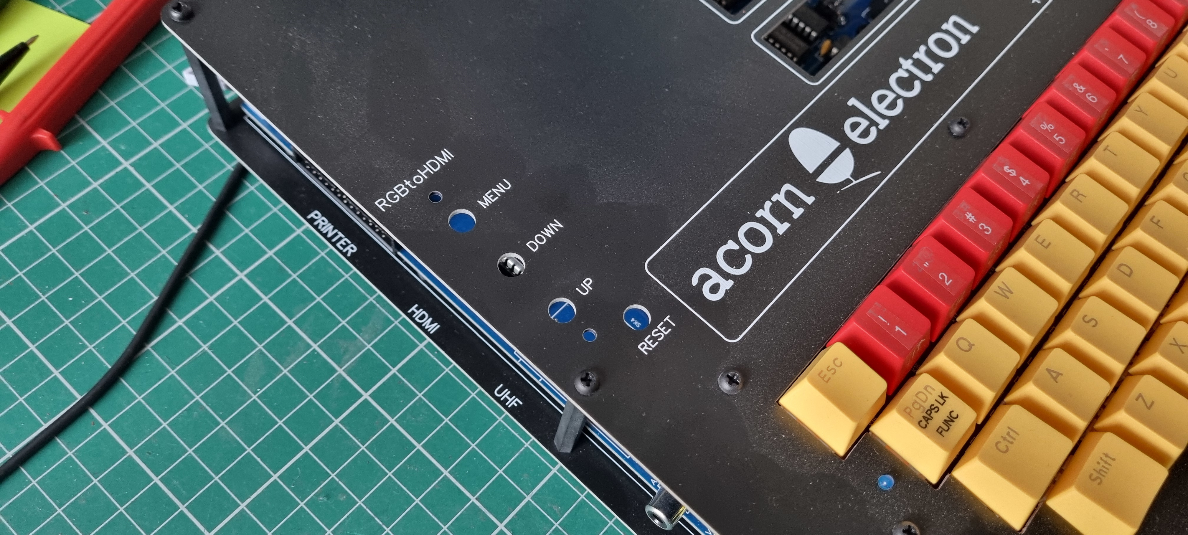
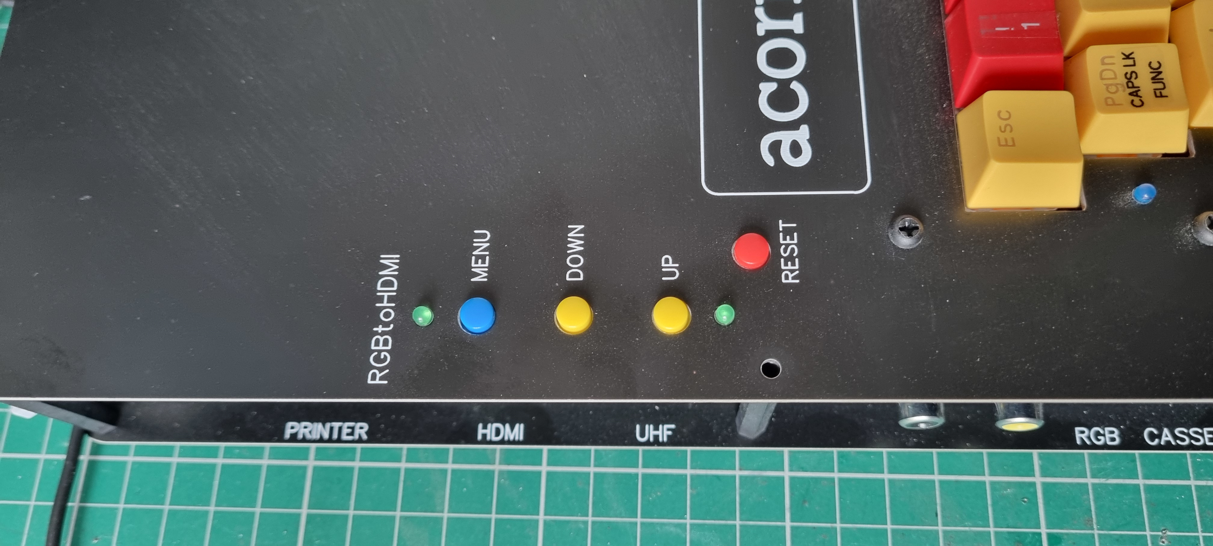
For the clone case the keyswitches have to be fairly tall versions so the keycaps fit neatly under and through the top of the case.
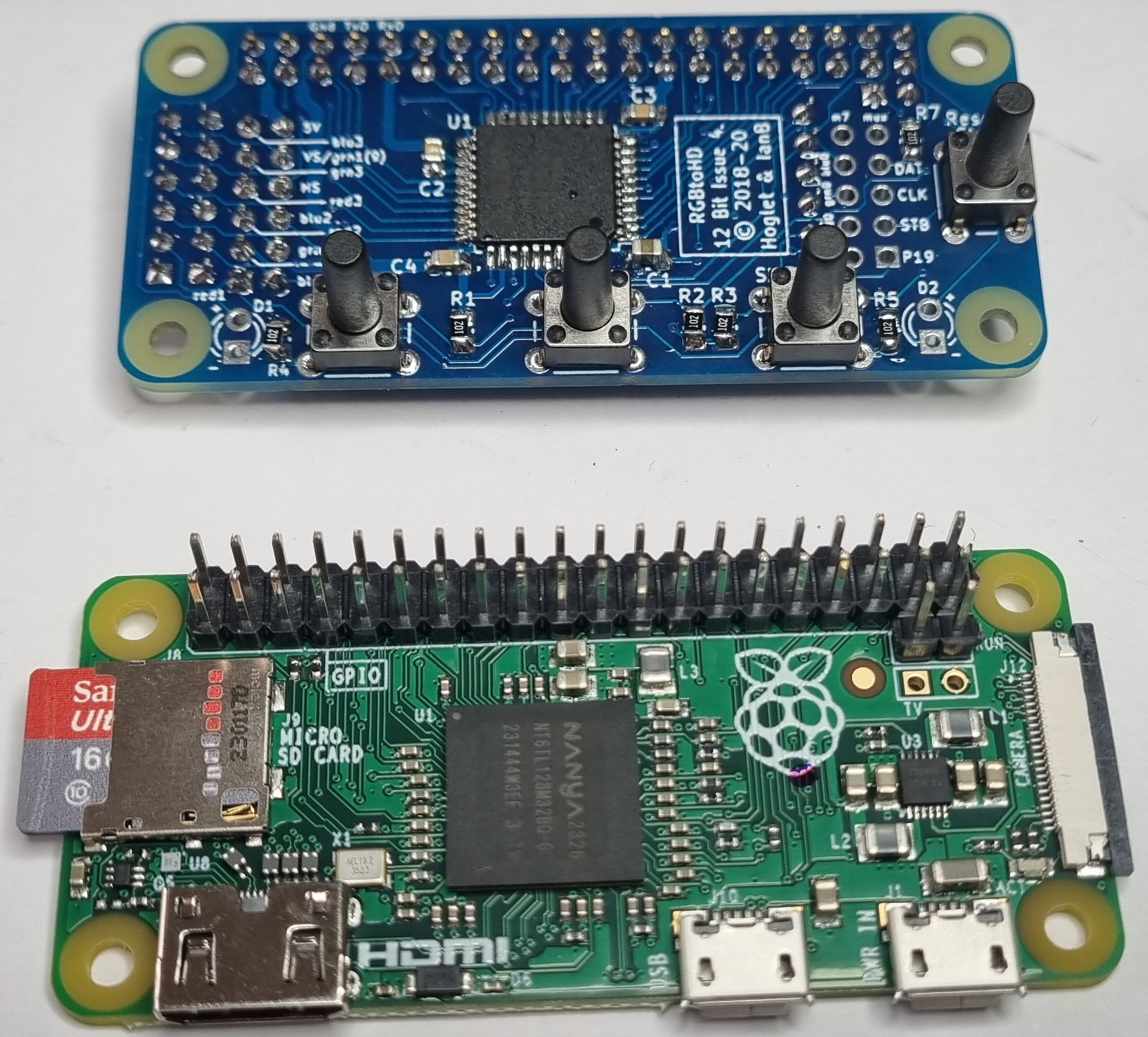
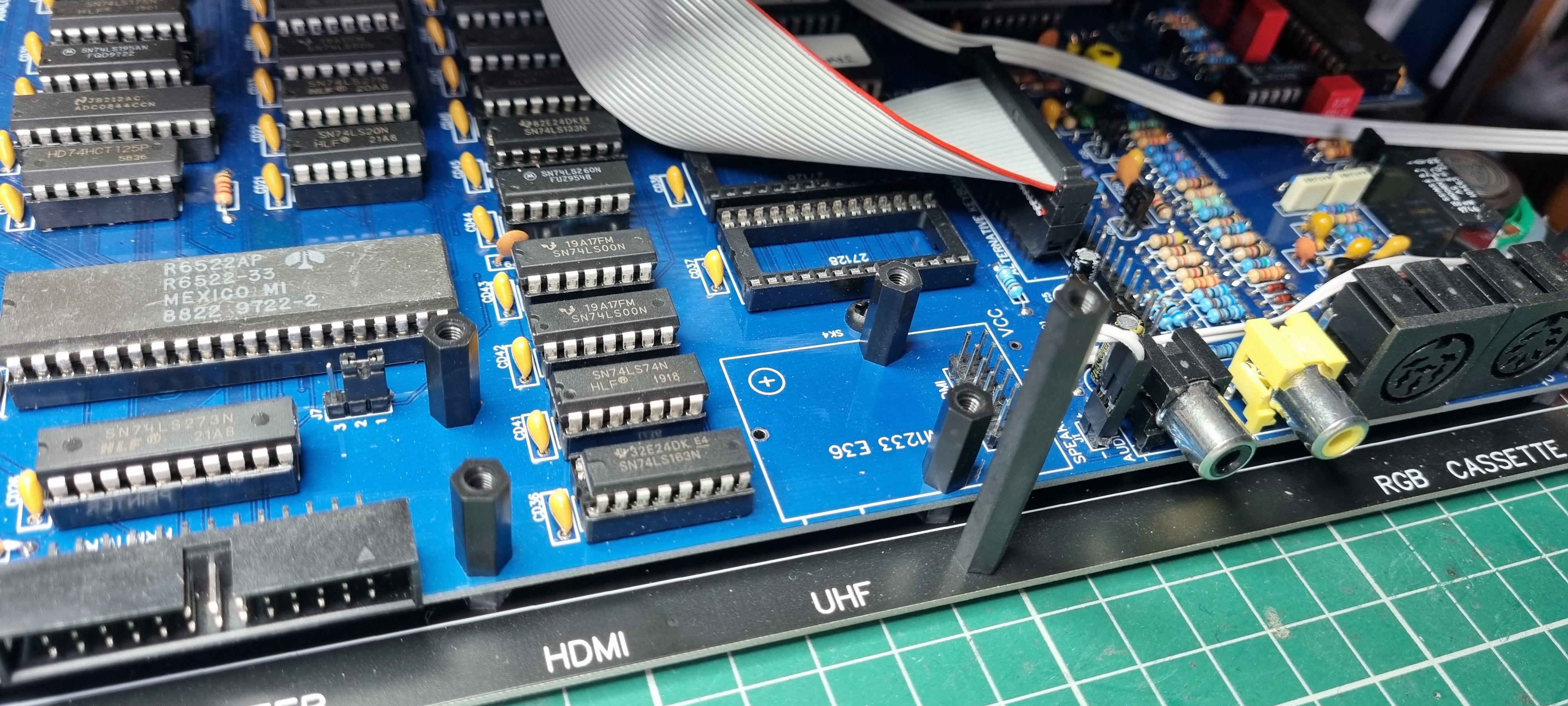
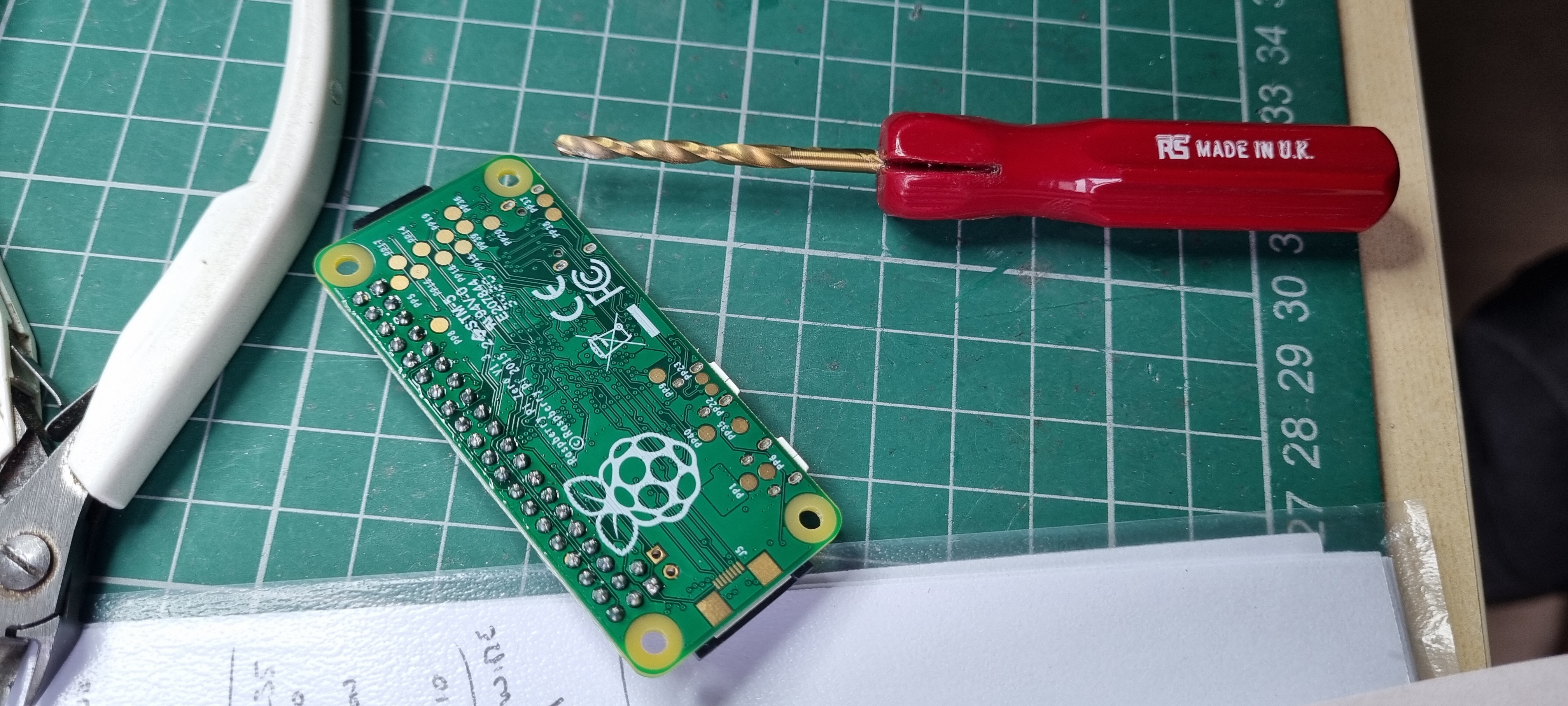
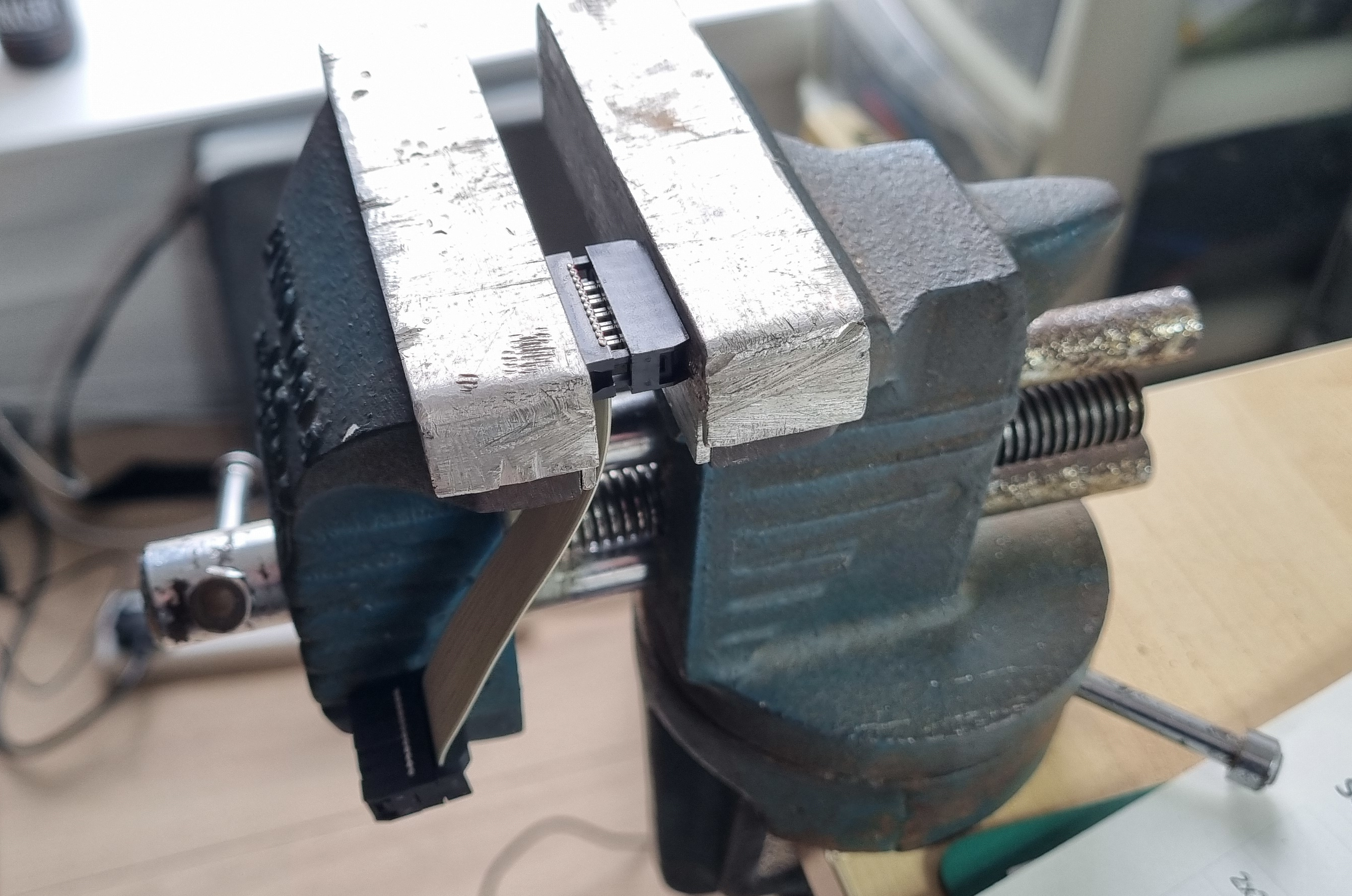
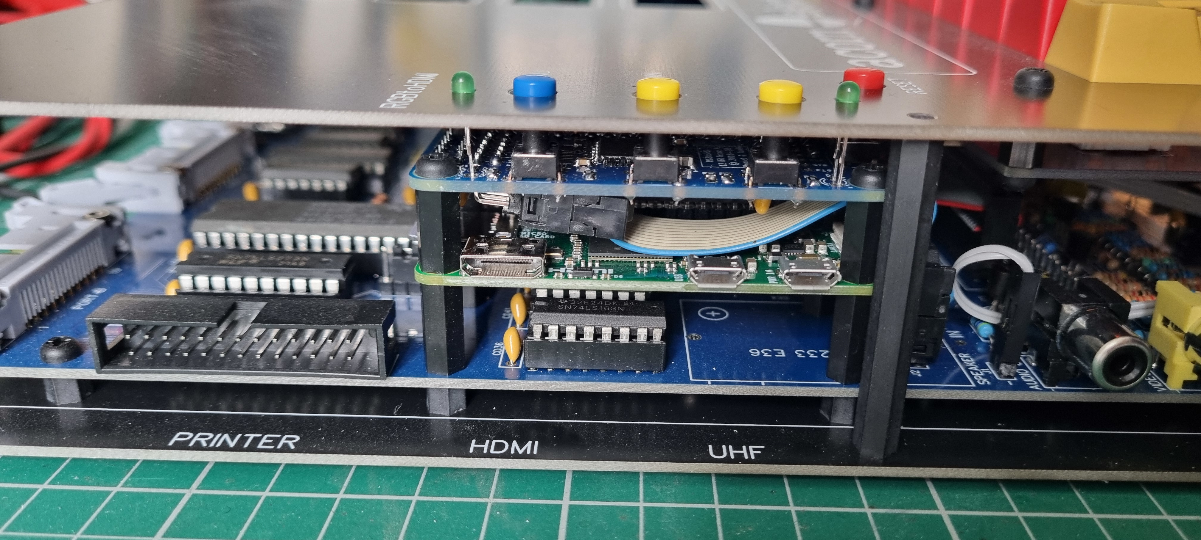
I have added pillars on the clone motherboard. I have used M3's throughout so I have to widen the mounting holes on the Raspberry Pi and the RGBtoHDMI hat.
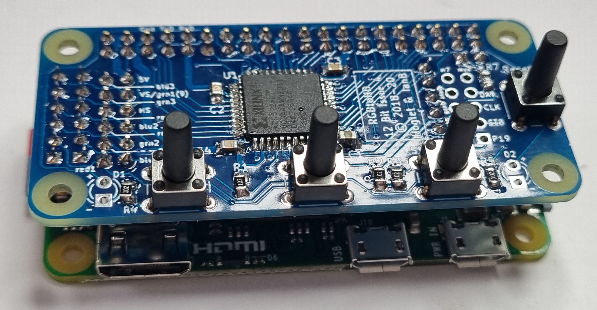
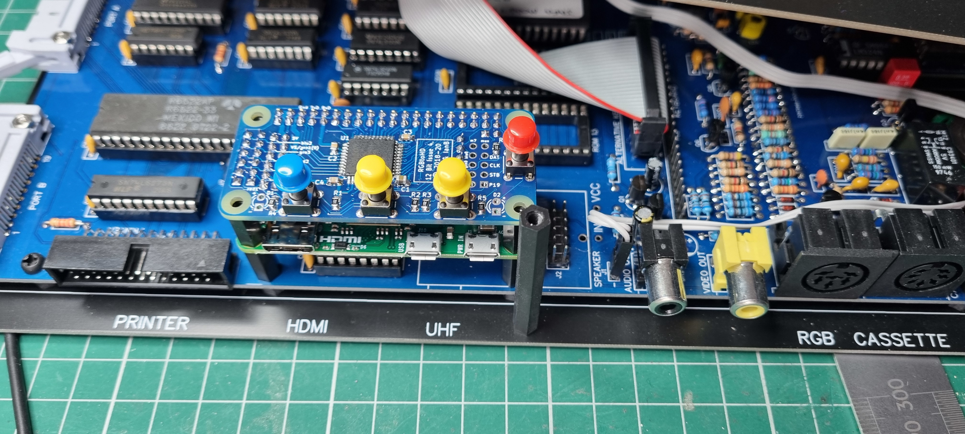
Then a test fit on the clone to make sure the pillar heights are correct and that the caps fit through the holes freely.
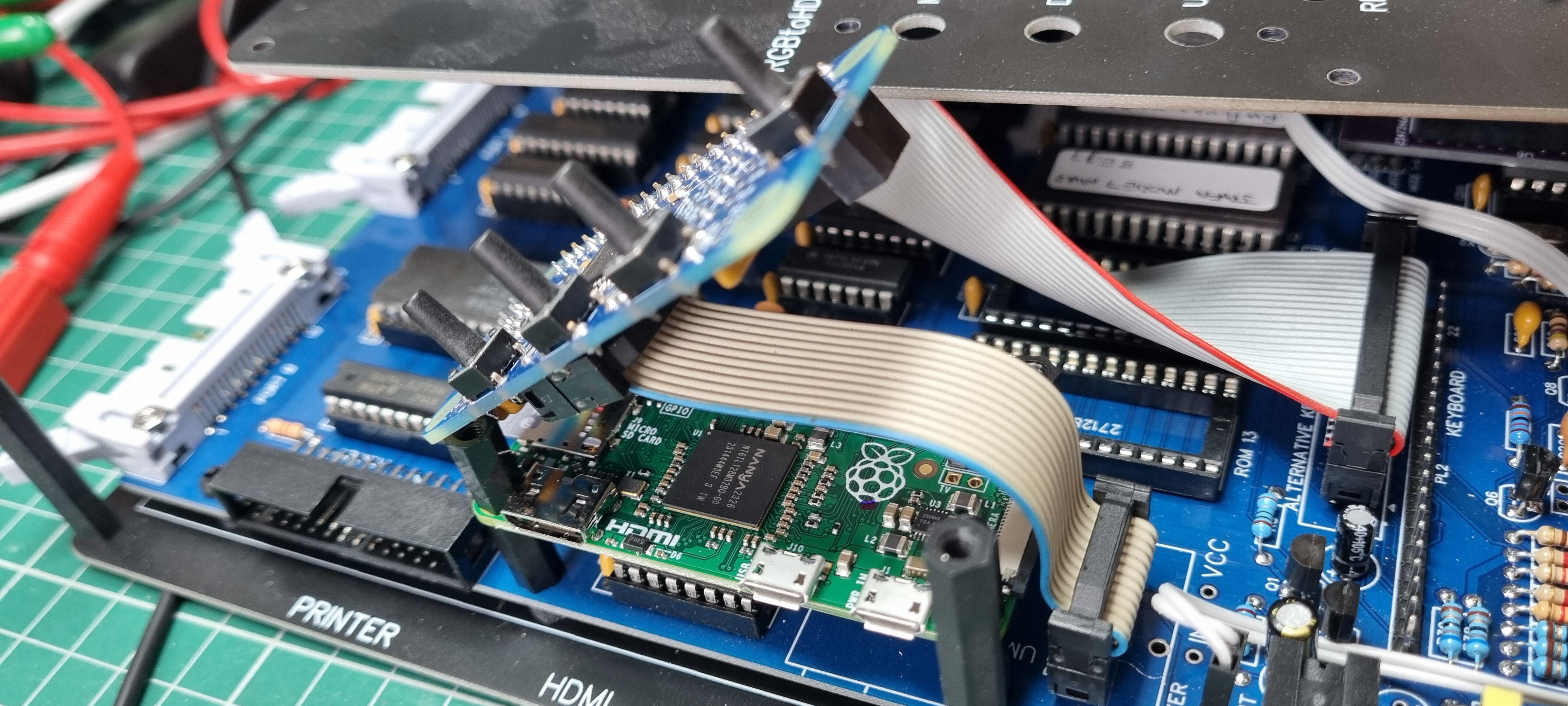
Next, is to make a small ribbon cable to connect the RGBtoHDMI hat to the motherboard.
Then the final fit.
At this point I noticed I hadn't fitted the two LED's so I placed them on the board and measured the height so they just fit through the top case.
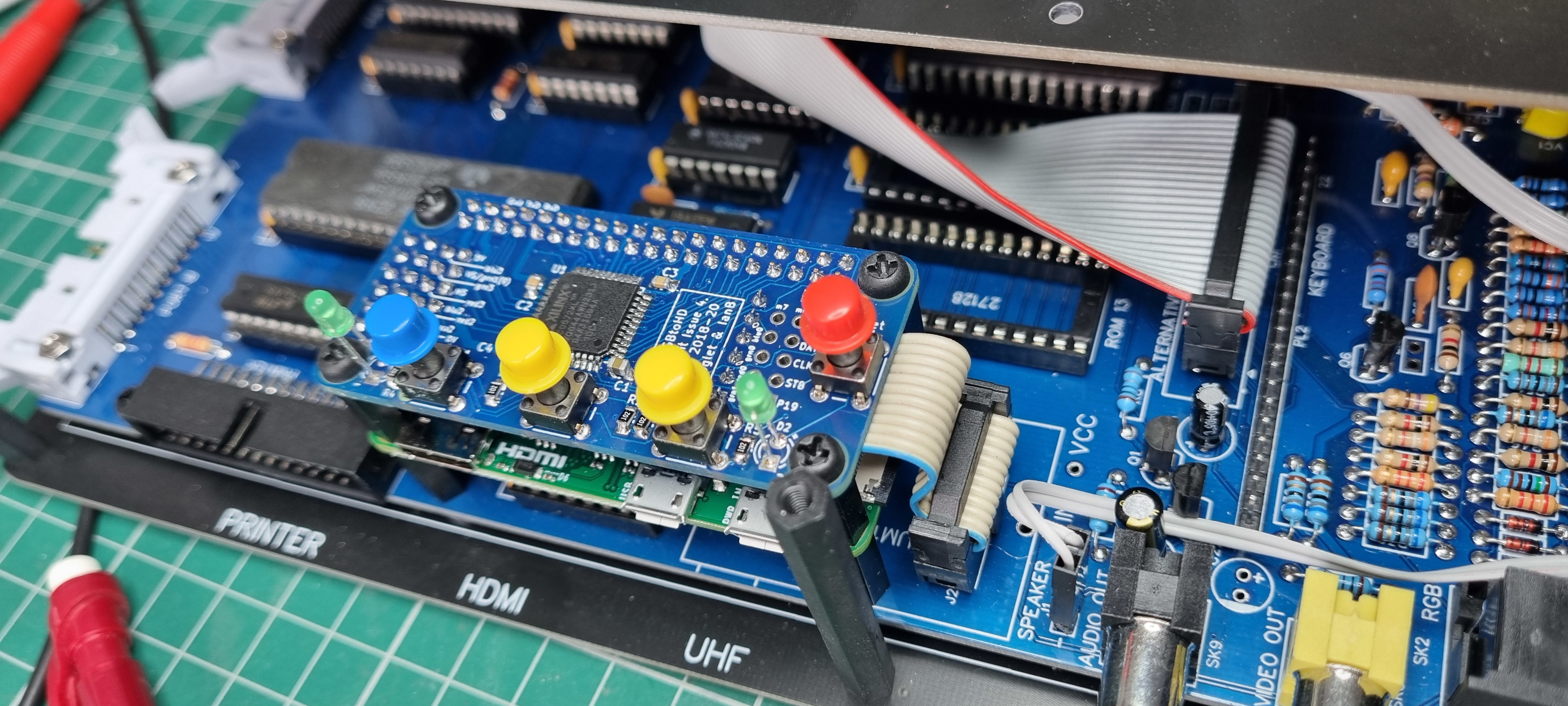
The finished installation.
Now onto the software. Visiting the RGBtoHDMI GitHub pages I downloaded the latest version of the software and copied it onto the Raspberry Pi SD card.
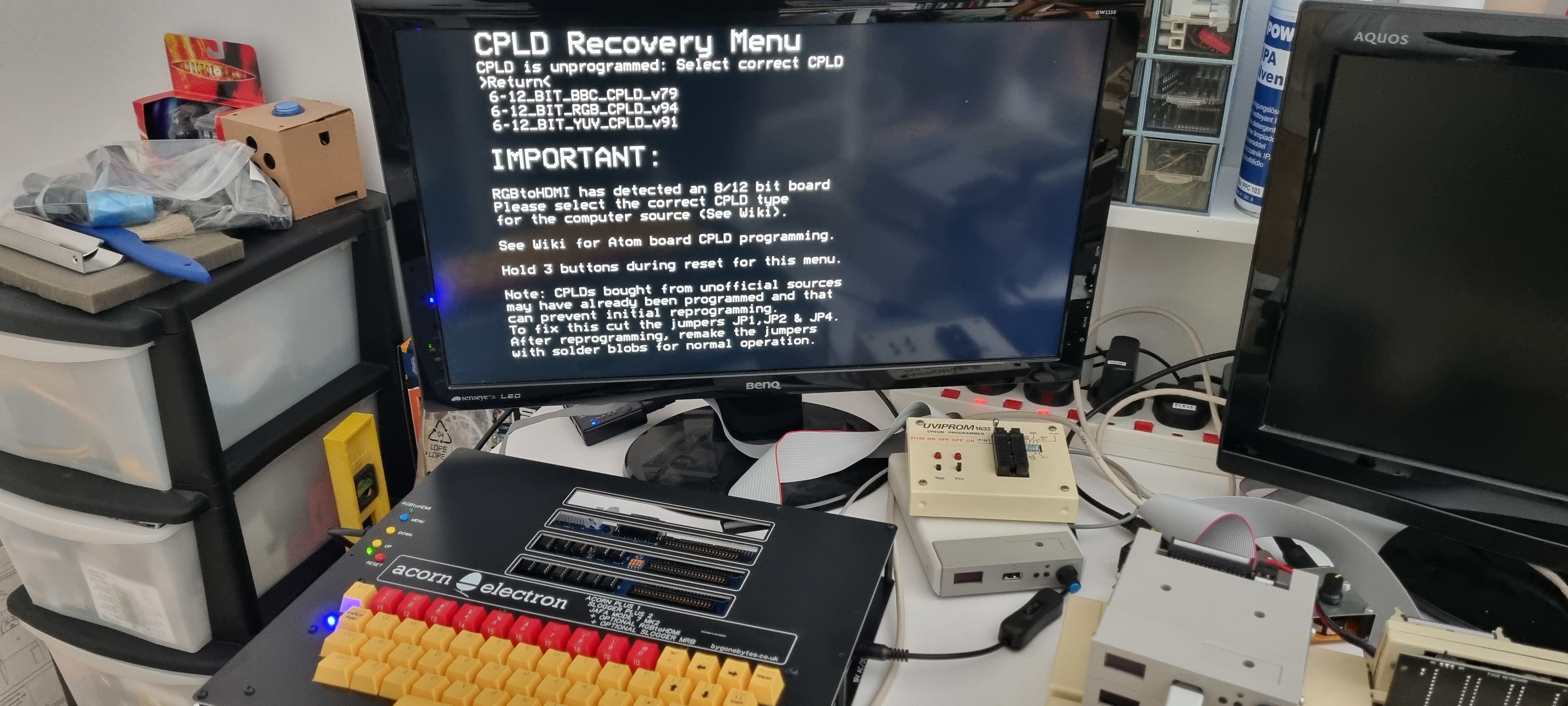
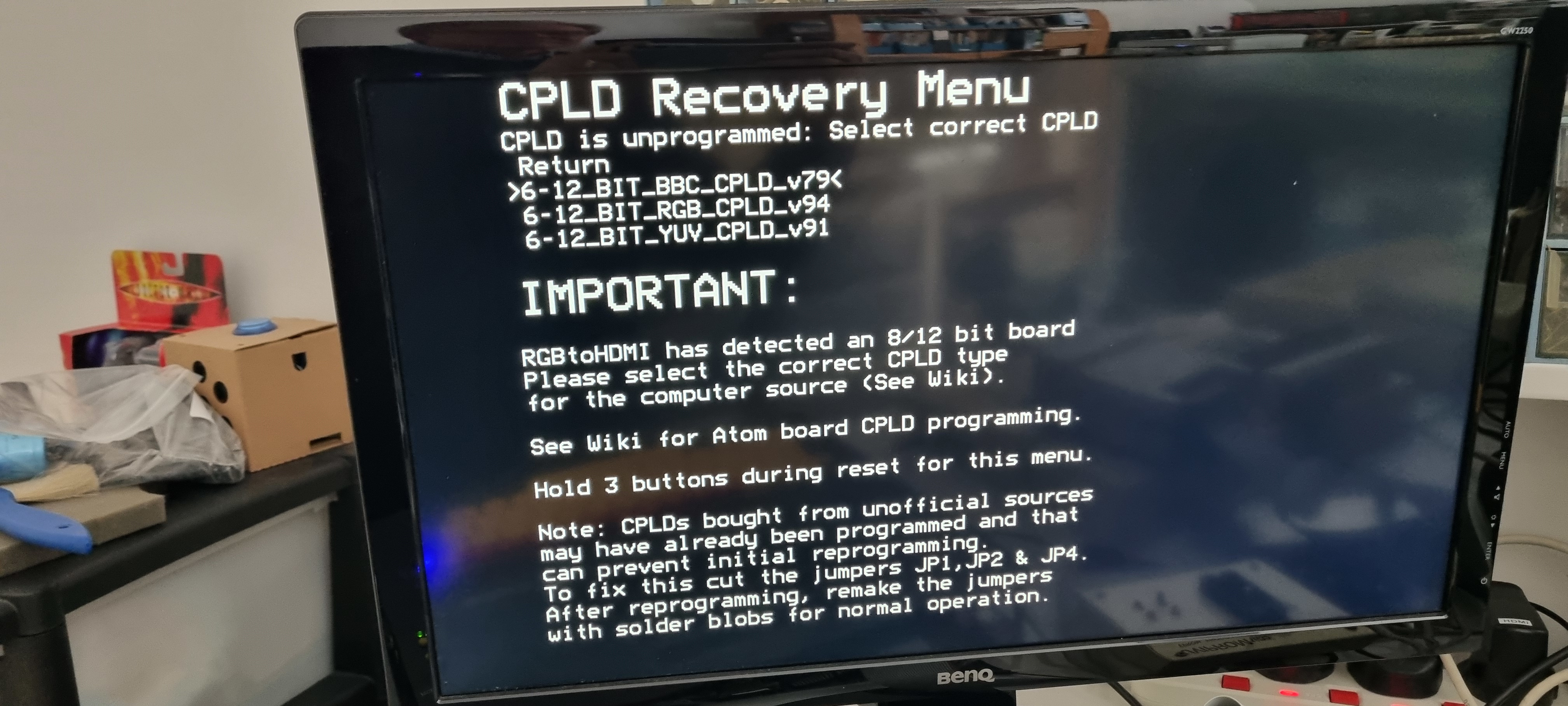
I connected the Raspberry Pi HDMI output to my monitor and powered on. The first screen you see lets you know the CPLD is unprogrammed and it gives you three choices. I chose the first one for the BBC.
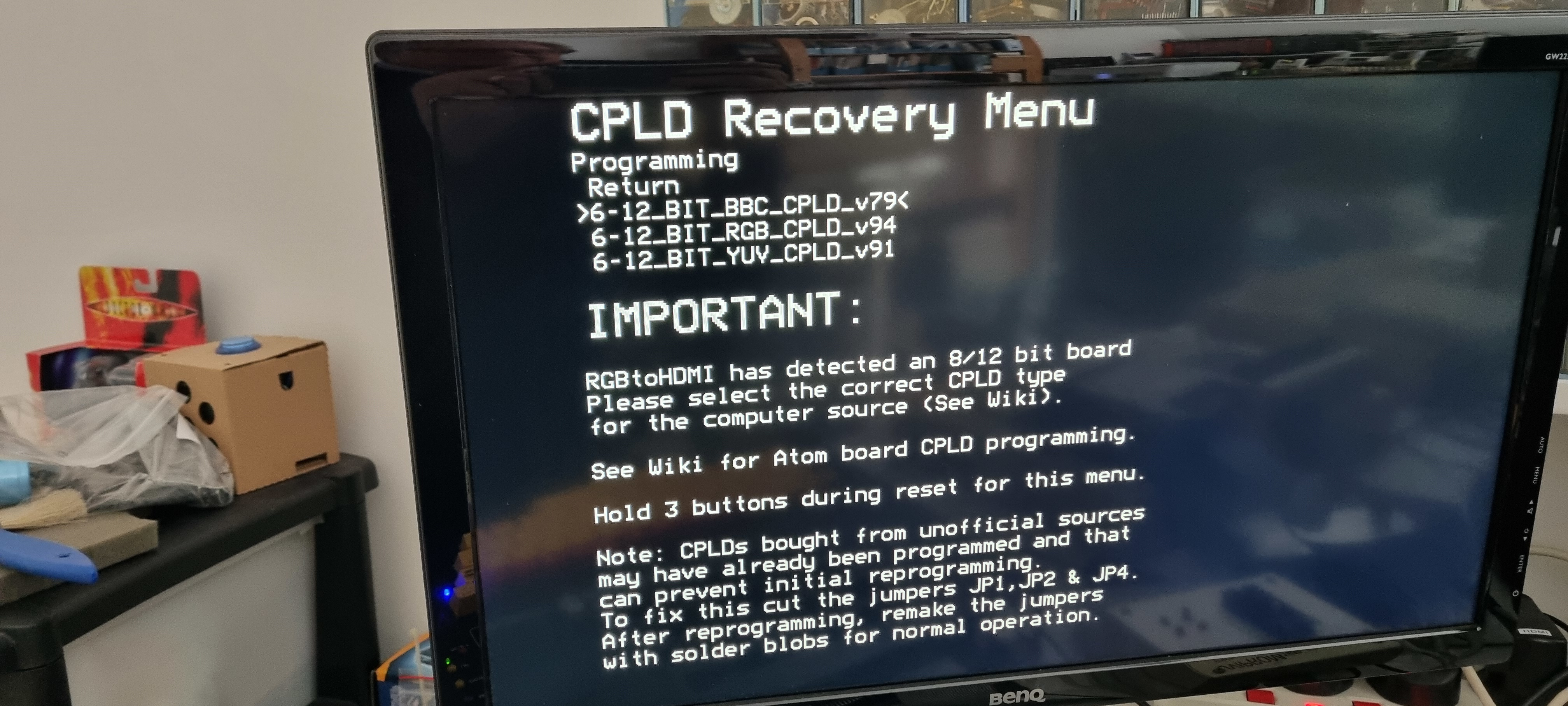
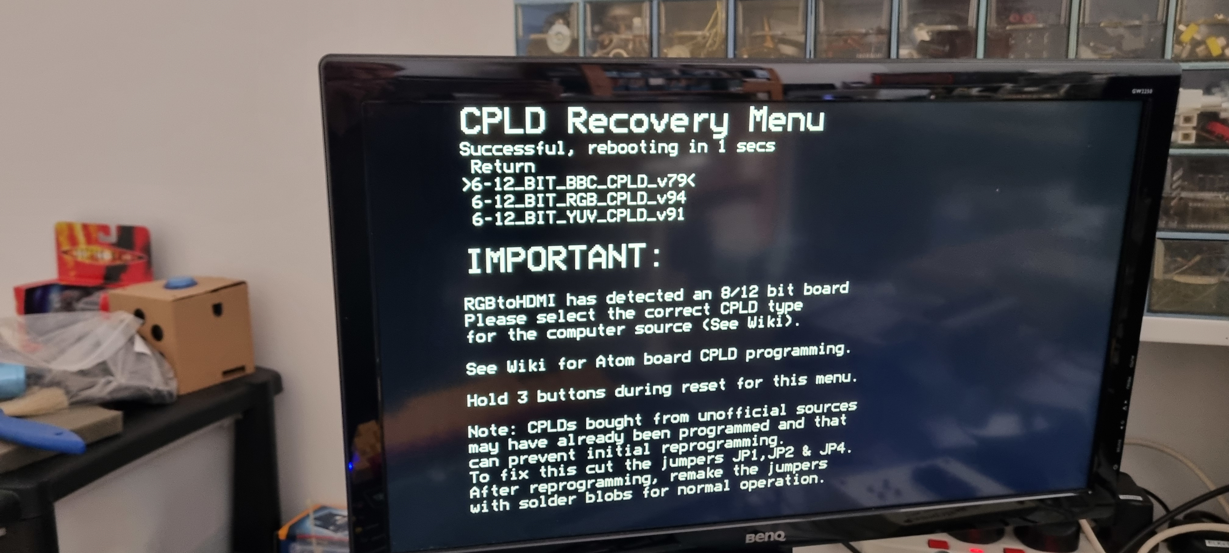
Then it lets you know it's programming, then hopefully it lets you know it was successful and reboots.
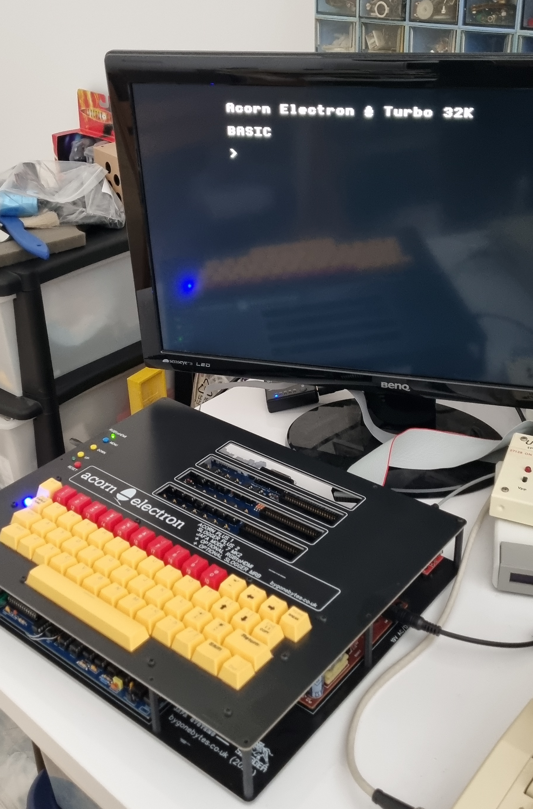
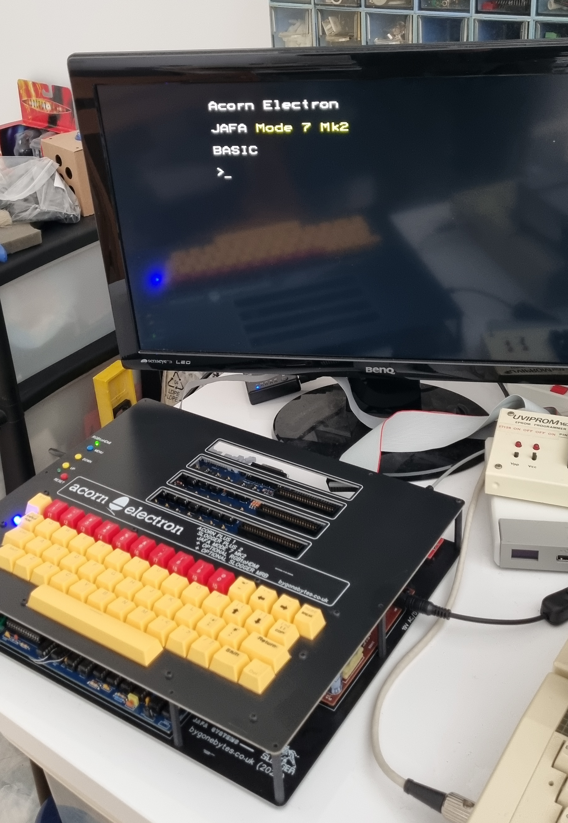
and finally I get the Electron sign on screen.
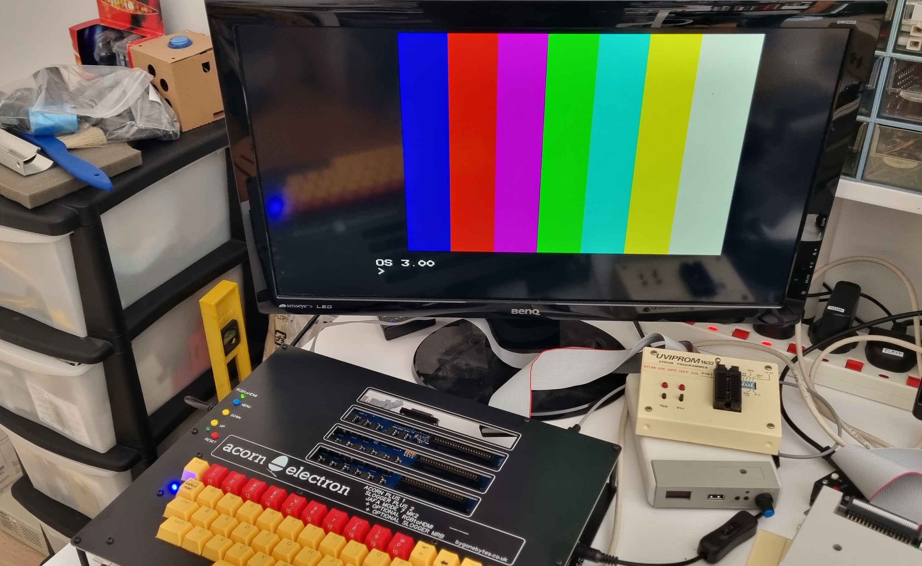
Turning on MODE7 and auto calibrating the RGBtoHDMI to get the best quality display. I used the *H.BARS command to fill the screen prior to calibration. Please read the RGBtoHDMI Wiki which gives a comprehensive guide to calibration and a whole lot more.
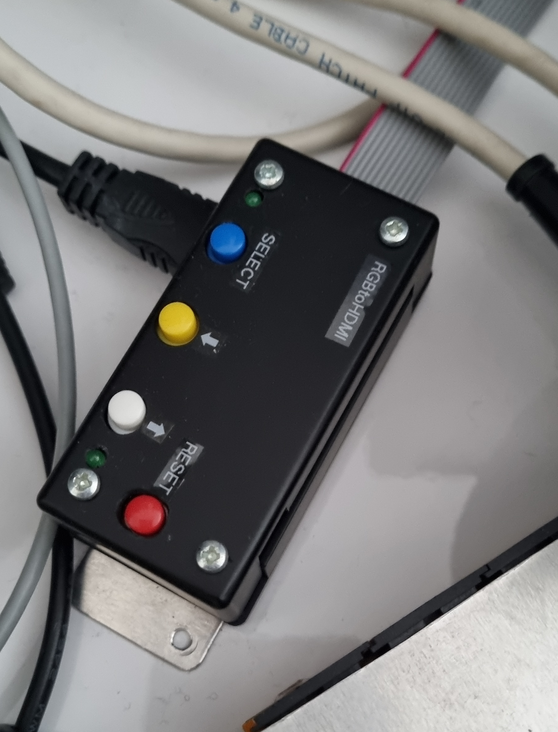
The second board I will keep partially complete so it can be built either as an internal board or one that can be fitted into a small box.
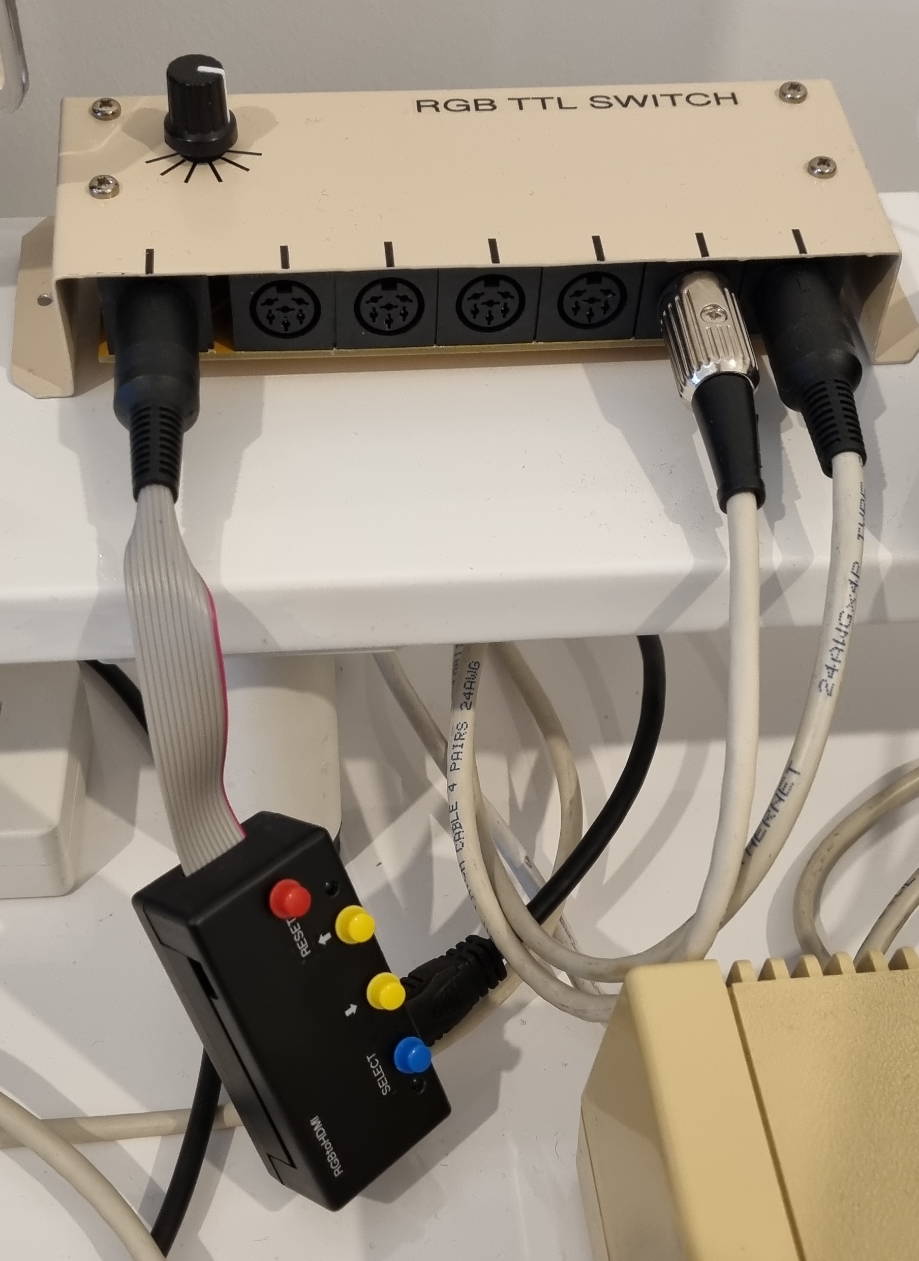
Here are a couple of boxed adapters. I used the template from GitHub to mark out the holes.