Prototyping
The Raspberry Pi Pico 2 has just been released so I thought it was about time I updated my 'Thermo Switch'. Since I built the 'Thermo Switch' my needs have changed, I no longer have to cool any Raspberry Pi's or Odroid computers as SETI has closed down and I no longer use my loft as a workspace so the problem of extreme heat is no longer there.
I first built the a thermometer/switch in May 2017 around the Raspberry Pi Zero which used LED's as temperature indicators, I then updated it using the first Pico, a battery backed RTC and a 2 row x 16 character display in January 2021. Now in 2024 with the new Pico 2 I think I'll update it again.
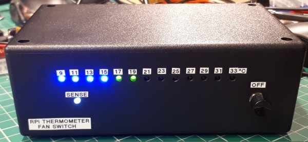
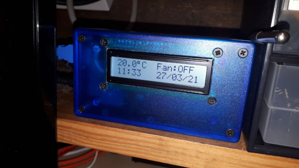
With each interation the thermometer gets a bit smaller..and this time it will be getting a bit smaller again. Both the above thermometers have a page dedicated to their builds elsewhere on this site.
The Pico 2 arrived just as I was going to experiment with an I2C thermometer board on the Electron. I had just installed a ROM in my Electron which enabled the real time clock (RTC) in the new Plus 6 and this ROM also has the code to send and receive I2C messages. Being easily sidetracked I thought I'd combine the Pico 2, an I2C thermometer sensor and an RTC board none of which were used in the previous incarnations. The previous two used a DS1820 sensor on a flying lead.
Here are the new boards I'll be using.
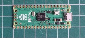
The Pico 2 (£5.76).
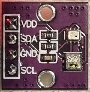
The AHT20 + BMP280 module for temperature, Humidity and Pressure (£0.92).
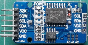
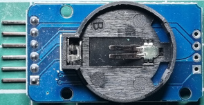
And a DS3231 RTC board (£0.99).
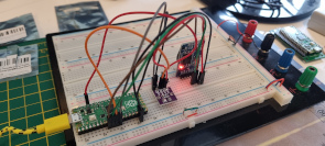
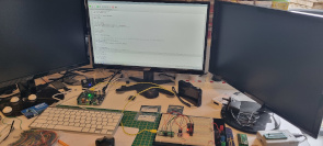
I made a start when I pre-ordered the Pico 2 by using a Pico 1 to transfer the I2C libraries from my previous Pico project, add new ones for the AHT20 module and alter the main.py script to read and format the data from the two modules.
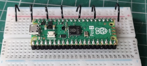
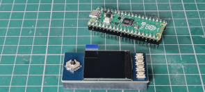
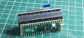
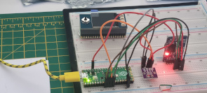
The Pico 2 and the new colour display. The display is the Waveshare SKU: WAV19650 1.3" IPS LCD 250x240 and uses the SPI interface. I chose this one as it was well supported in MicroPython and the Pico plugs straight into it.
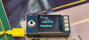
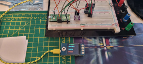
Adding the SPI display driver to the Pico 2 including the font option. The font option allows for three text sizes and the opportunity to edit character shapes. This is me just getting used to altering the text, position and colours. There is also a graphics option which I may use to draw a bygonebytes splash screen.
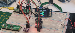
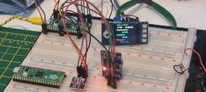
Time to transfer the data output from Thonny to the display starting with the time and date. This involved splitting the display from the Pico to enable access to all the interfaces on the Pico. That was fairly straight forward but when incorporating the temperature sensor there seemed to be a conflict between the I2C and the SPI interfaces as the I2C data transfer was timing out. Moving the I2C in the script and onto different pins on the Pico fixed this issue.
Now that all the data is being displayed I noticed that the degree symbol was incorrect.
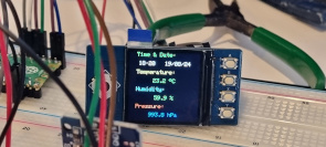
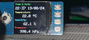
As the font option allowed me to search through and edit a single character I altered it from a grid of dots to the degree symbol. Next was to make it more readable by altering the text sizes. Later on I made another change to the shape of the degree symbol to make it round rather than oval!
The font option uses a lot of memory which if I used a Pico 1 I would probably have to edit out the unused characters, I came across this when building the Train Describer Display Tester.
Final build
To build this into a usable piece of kit it has to be assembled on a PCB and mounted in a case. With the Raspberry Pi 5 replacing the now retired Raspberry Pi 400 it was very well suited to designing the PCB and the case.
This was my first project using the PI 5 and I noticed a few shortcomings, firstly it will close all programs and log off when I switch my monitor on..very annoying, secondly I cannot copy and paste files in File Manager. I can drag and drop to move a file but that's it - fixed with recent update. Thirdly Scrot the screen grapper doesn't work however I did get Grim to work and I linked it to the PrtSrn key on the keyboard...I'm sure they are all OS Bookworm & Wayland issues.
Anyway enough grumbling..on with the design..
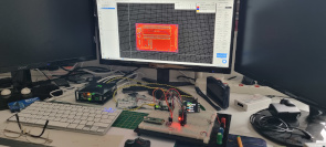
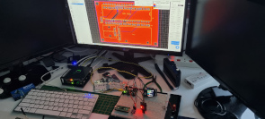
My first design included an output to drive a relay, a fall back to the earlier design. I removed it as I new I wouldn ever use it but I left a header just in case. This one change made the board about 15mm smaller. I retained all the button inputs from the display just in case I want to add some menus but I had to assign them to different GPIO pins. The Pico 2 and the modules are on one side of the board and the display on the other, all will be socketed.
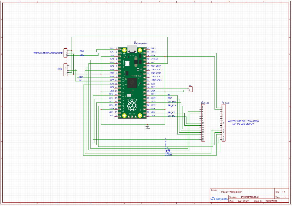
The Circuit Diagram.
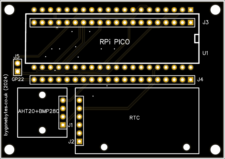
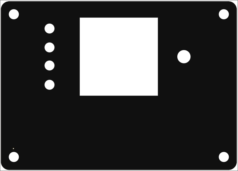
This new case looks familiar and measures just 71mm x 51mm.
Boards in manufacture..
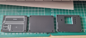
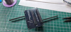
The board and case pieces arrived and assembly starts. I used spare pin strips to ensure the correct angles and spacing for the Pico socket pin strip.
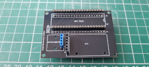
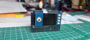
All the sockets soldered in place but I had to replace the blue one as it should have been a turn pin socket. The display simply plugs onto the board.
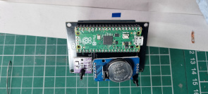
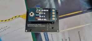
The Pico and sensors plug in too. I need to sort out the correct length of support pillars for the sensors to straighten them up. Time for the power on test, happy to see it worked first time.
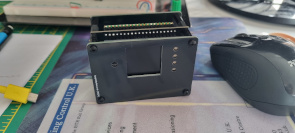
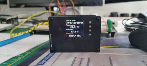
Assembling the case round the circuit board and checking the apertures are all in the correct place.
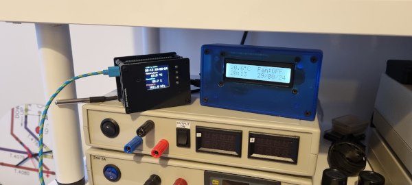
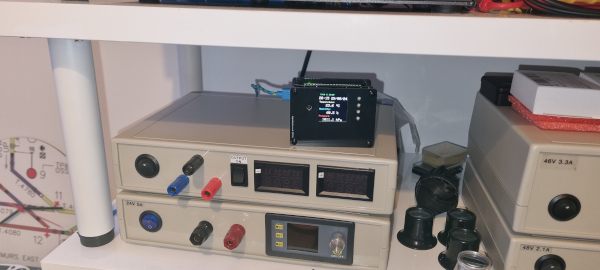
The old being retired and the new in place.
Afterward
I noticed on the picture above both thermometers do not agree with each other, roughly 3 degrees higher - odd. I had noticed a difference during testing but I put it down to it being in a different place and height in the room. With them beside each other it shows there is an overall discrepancy of 2 degrees. Some calibration is required! I brought my house thermostat through and it agreed with the old one so I added an offset to my programme and now all three display the same reading.
The script, just copy everything onto the Pico once you have set it up with the Micropython uf2 file and the Gerbers for the PCB, front and back case panels.