Electron Clone v2
I have been considering for some time some changes (improvements!) to add more features and to reduce the chip count. The chip count is roughly the same as a BBC Master!
Here are some of the changes I've been thinking about:
Add:
A joystick Port - possibly not?
Just after playing with an SD card adapter - MMFS/2
Include the MRB directly on the PCB
USB power ports directly on the PCB
Remove:
The UHF modulator
The Cassette interface
Remove composite video port
Remove the audio port (I added)
Remove the Printer Port?
Expansion connector.
I need more PCB edge real estate for connectors but I also want to reduce the overall size of the PCB.
To shrink the PCB size I could reduce the number of IC's - I could replace approximately twelve 74 series with three PAL IC's. Nine less..
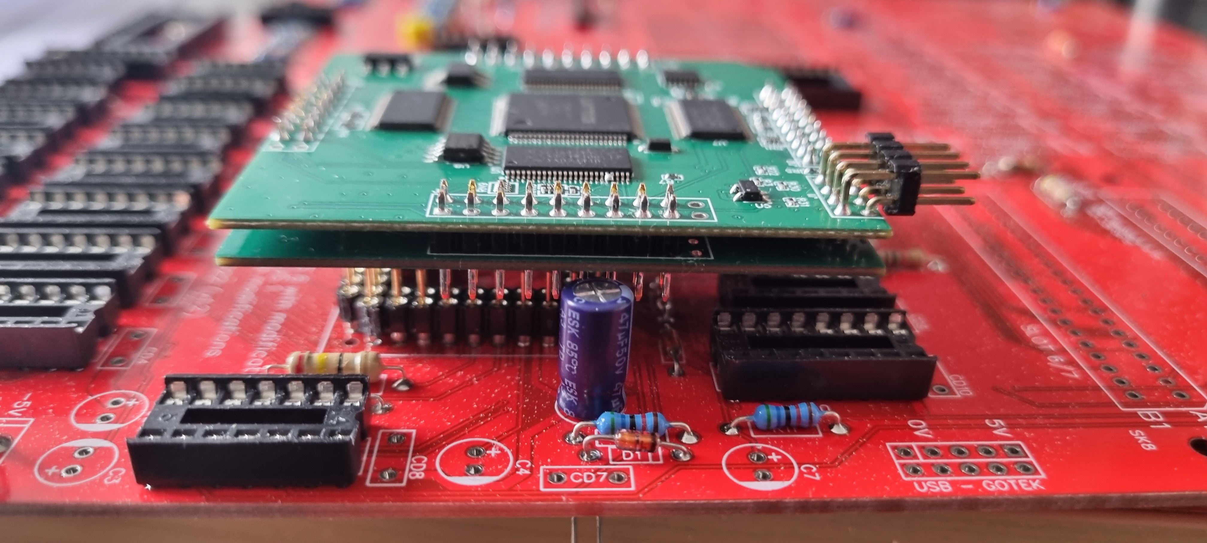
And to add to the mix a new ULA replacement has been announced on Stardot. To prototype these changes I am building a Clone v1.2 board to try out some of these changes particularly the fitting of the ULA and the IC reduction ideas before committing to a new PCB.
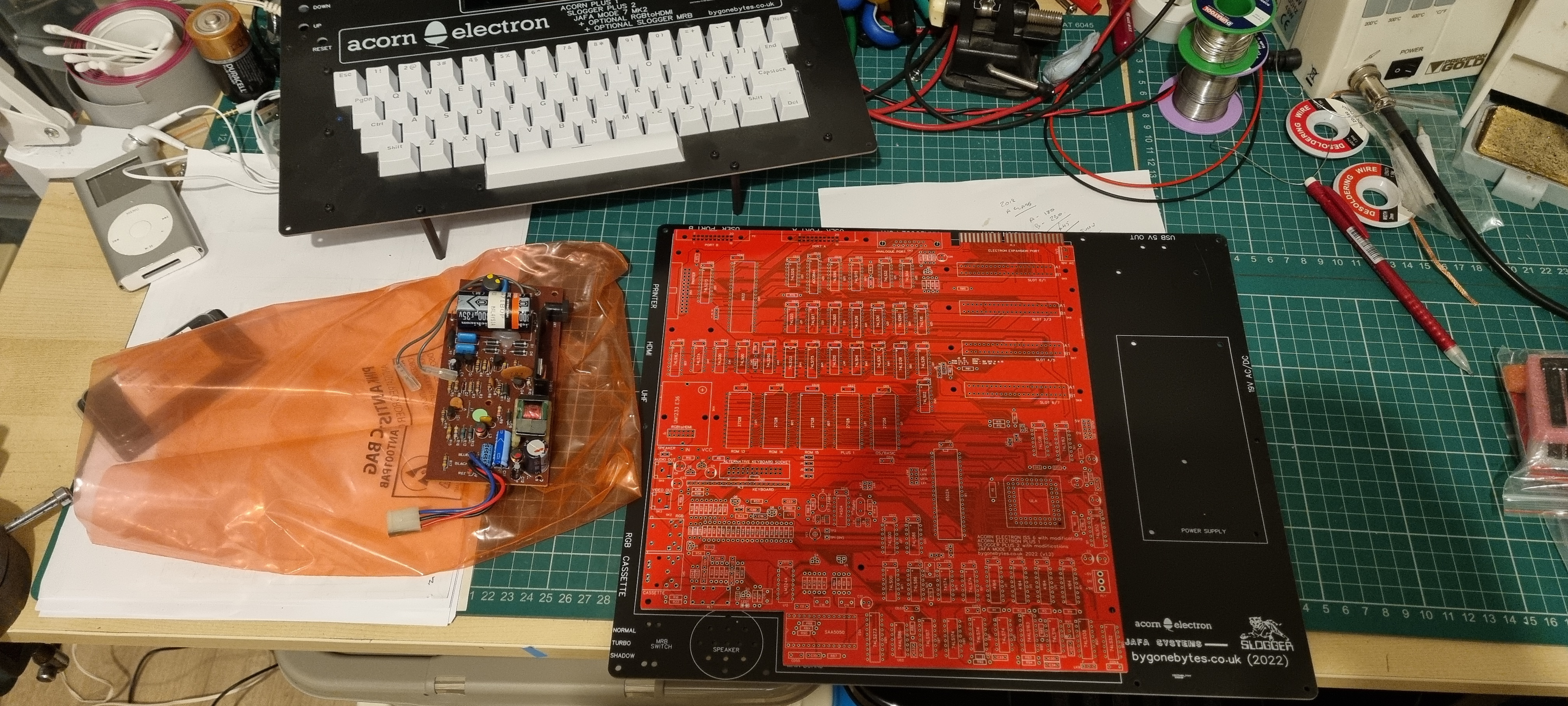
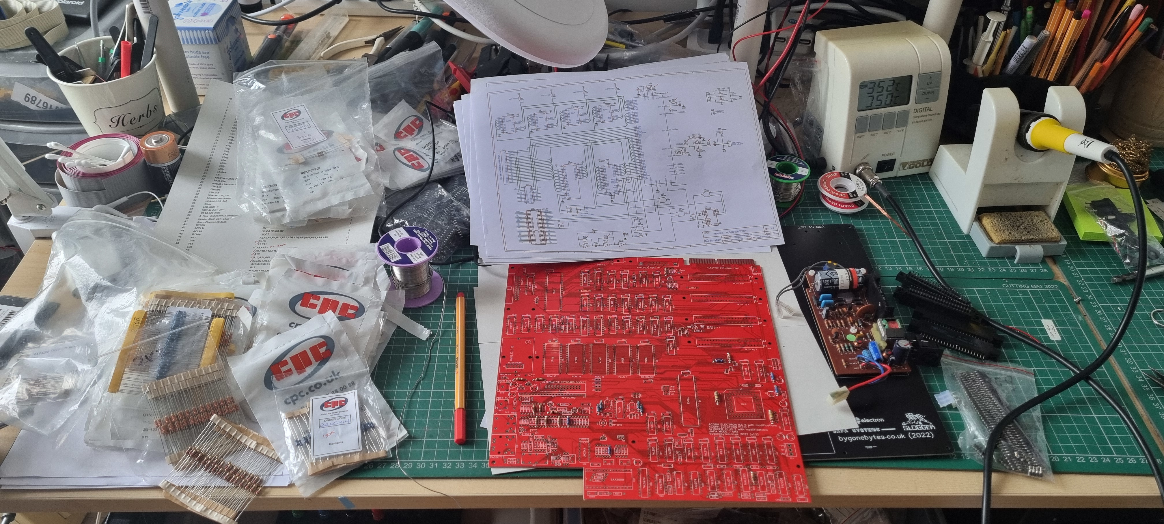
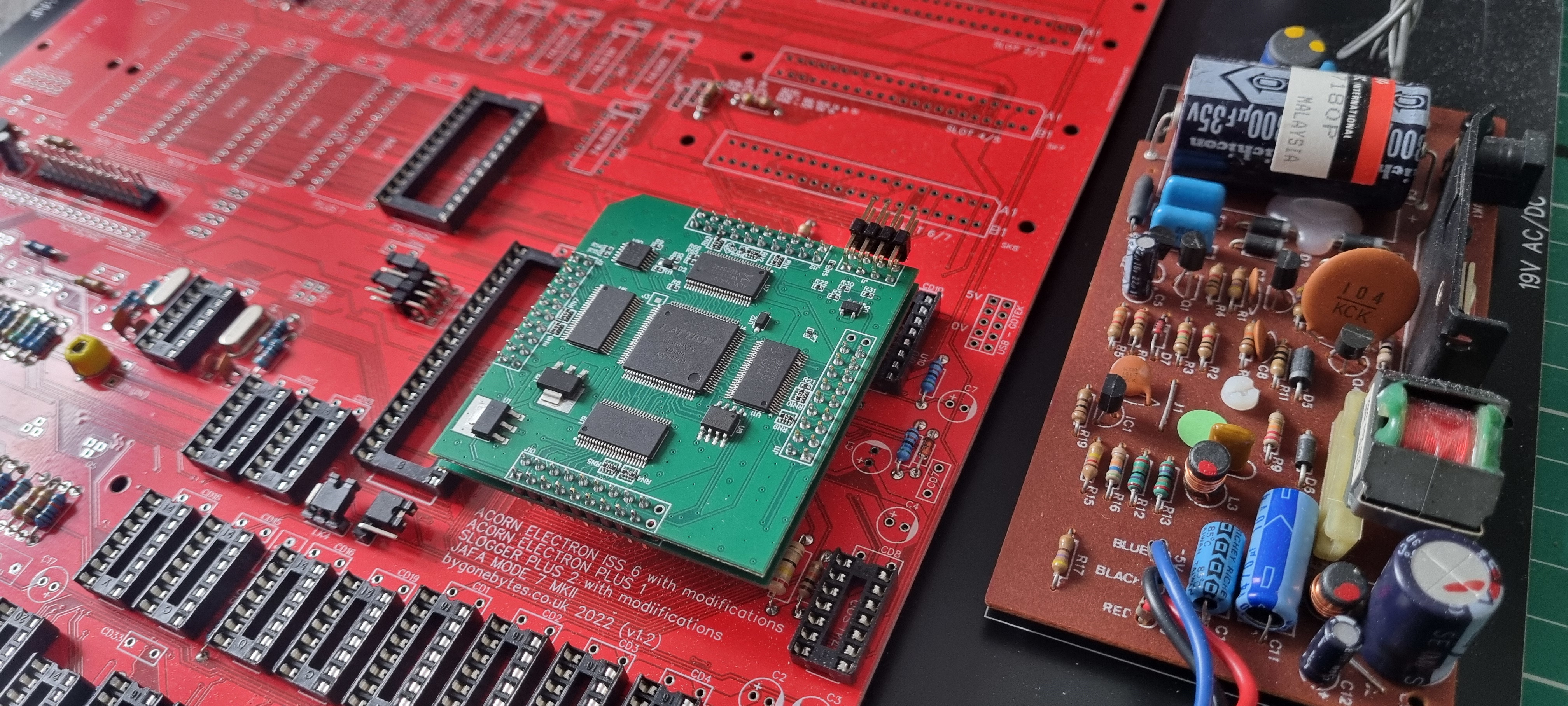
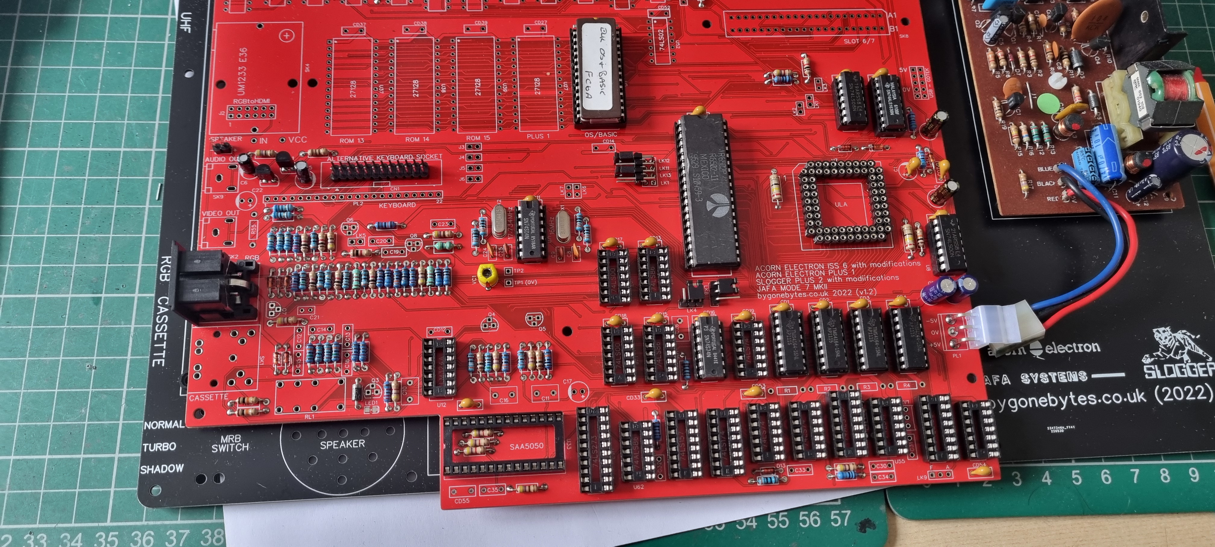
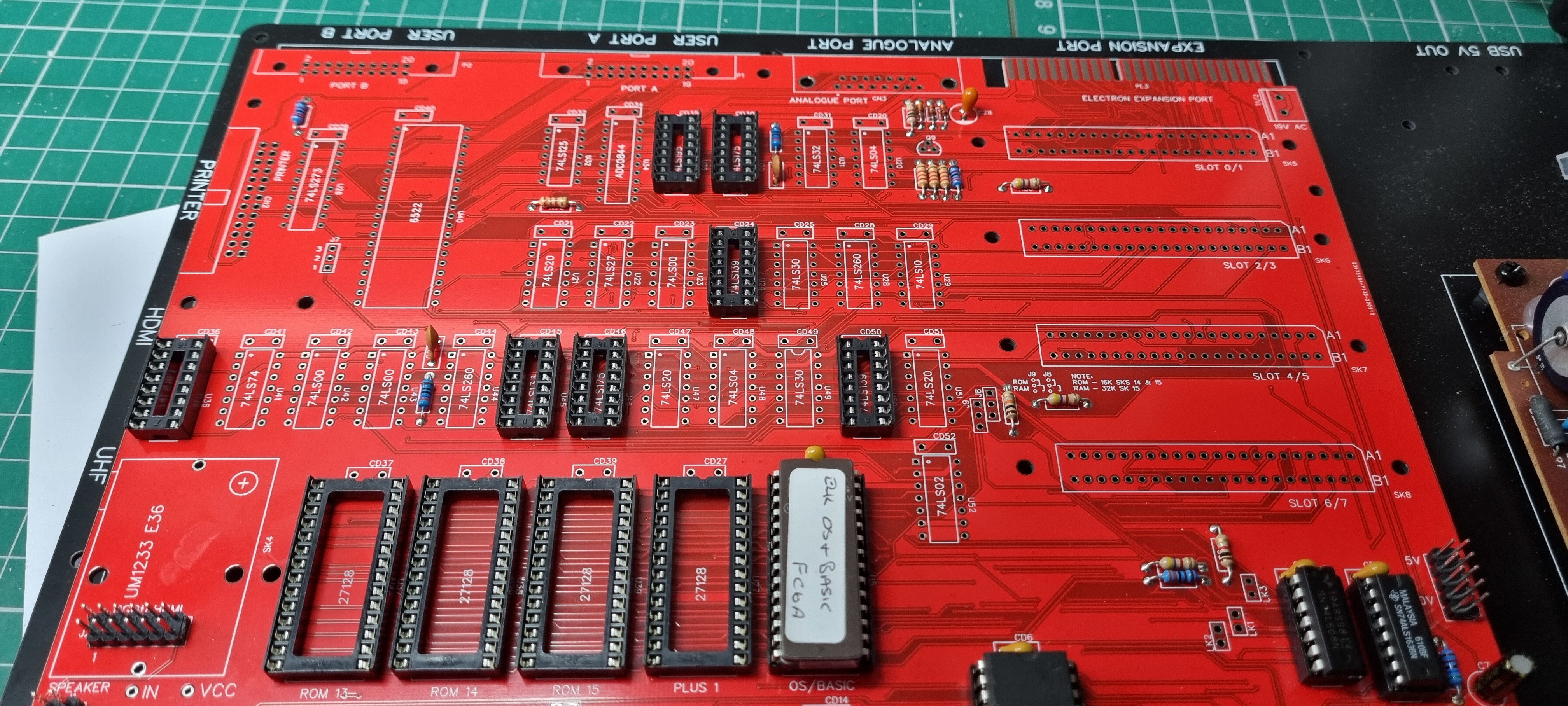
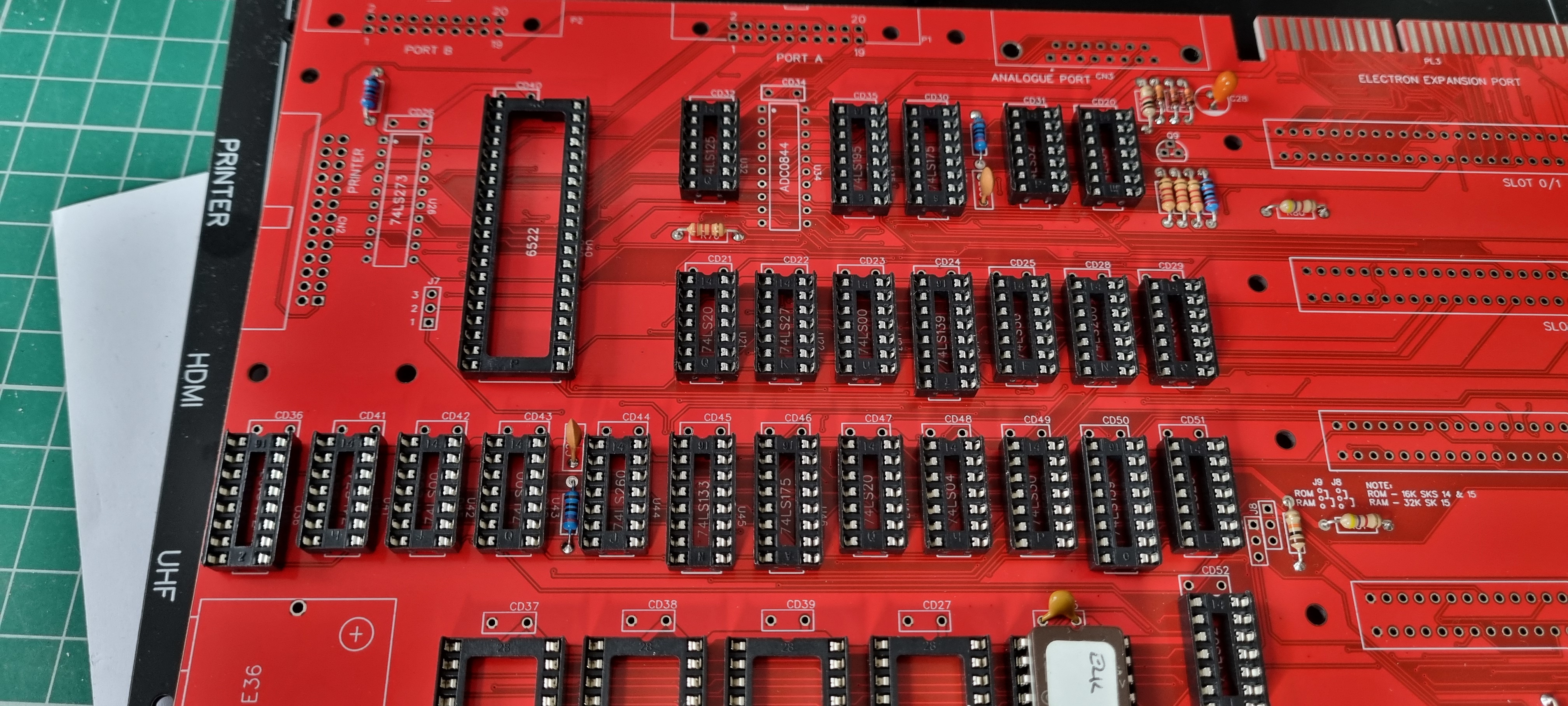
Looking out the major parts to start building the test board and also looking at chip reduction.
Starting to solder in the resistors and then the IC sockets.
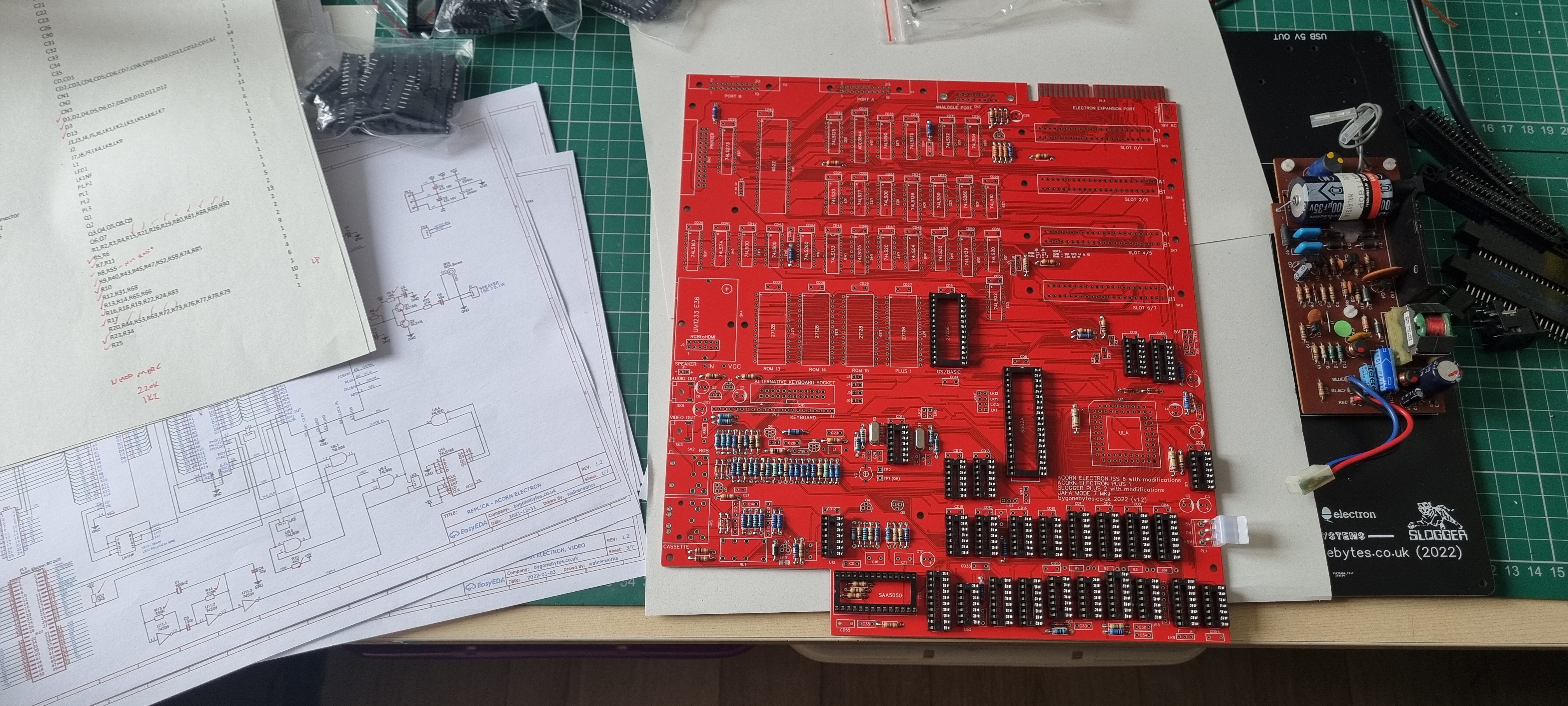
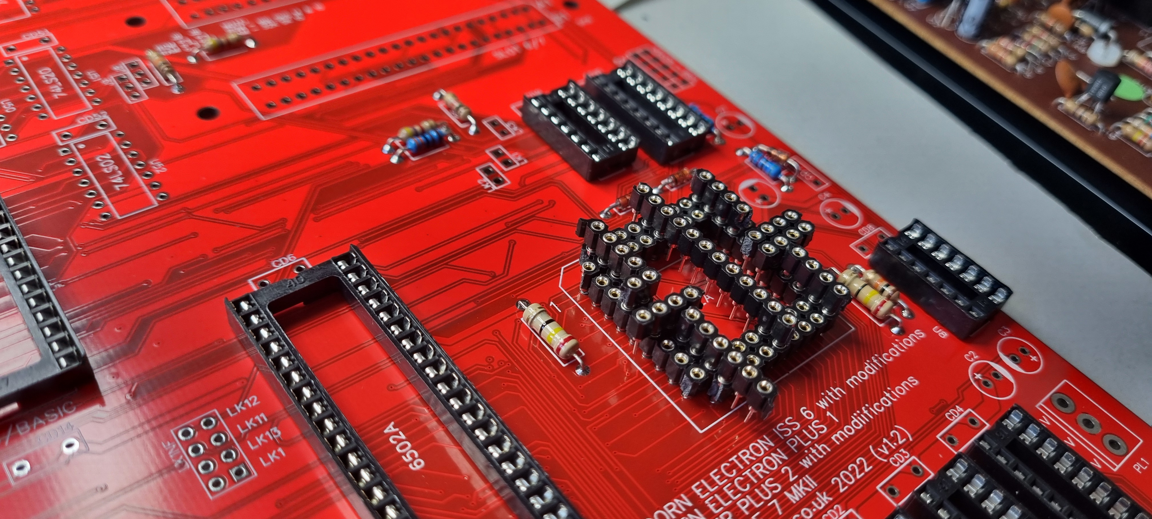
Creating the 68 pin socket from single in line socket strip using off cuts to ensure all pins align.
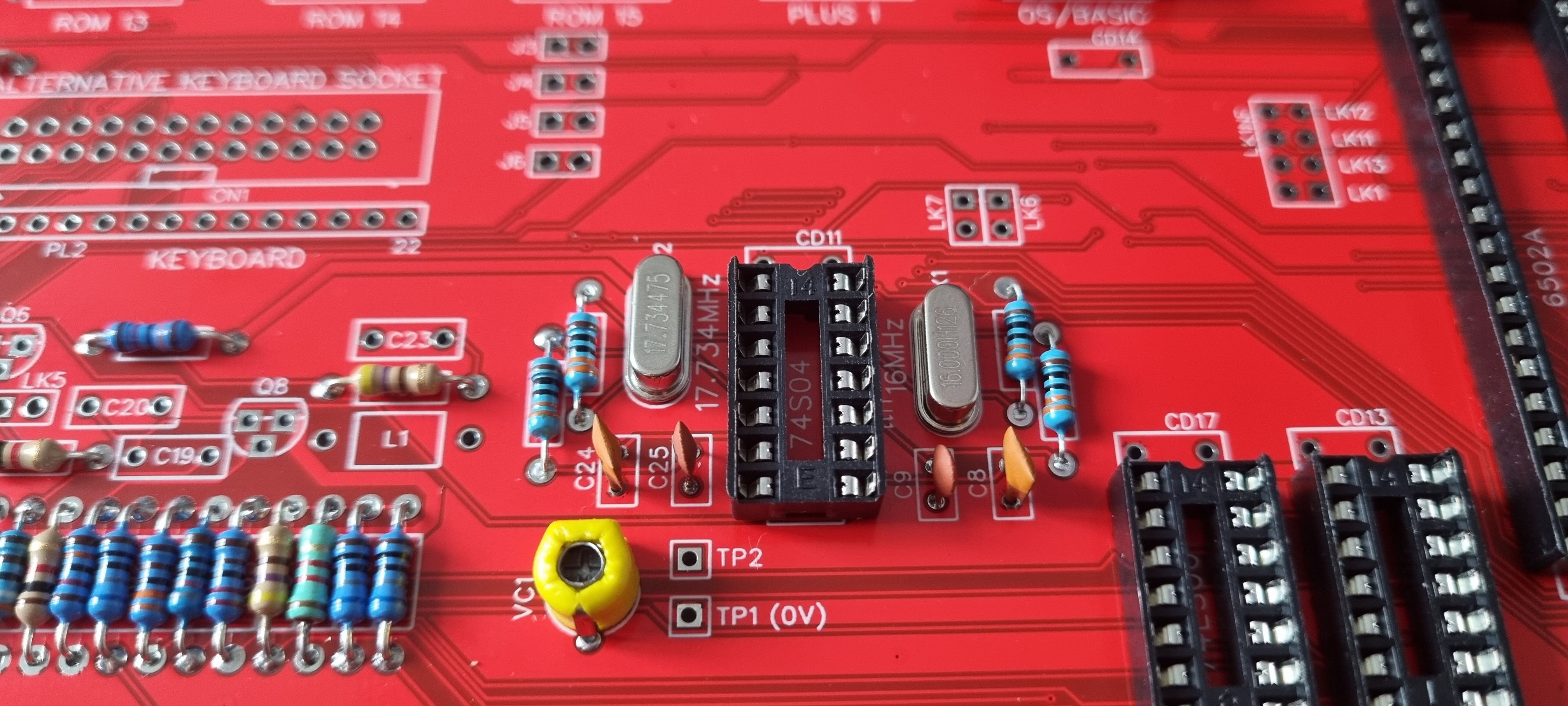
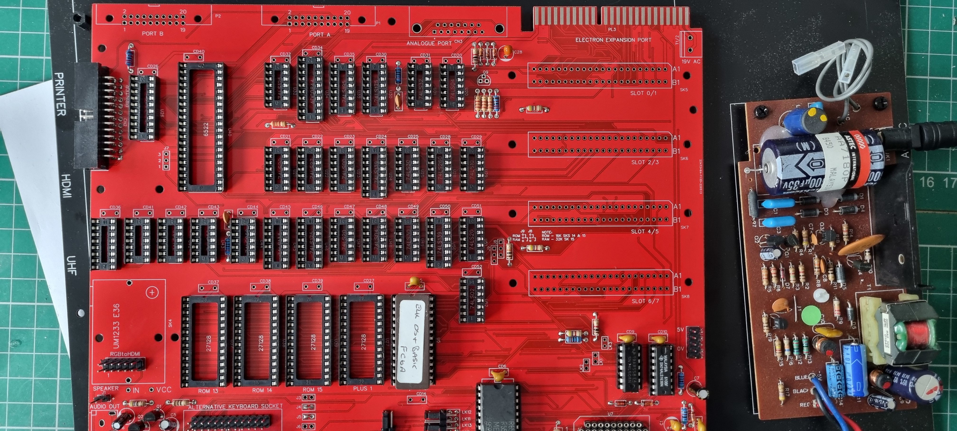
Adding in the oscillators and the RGB socket.
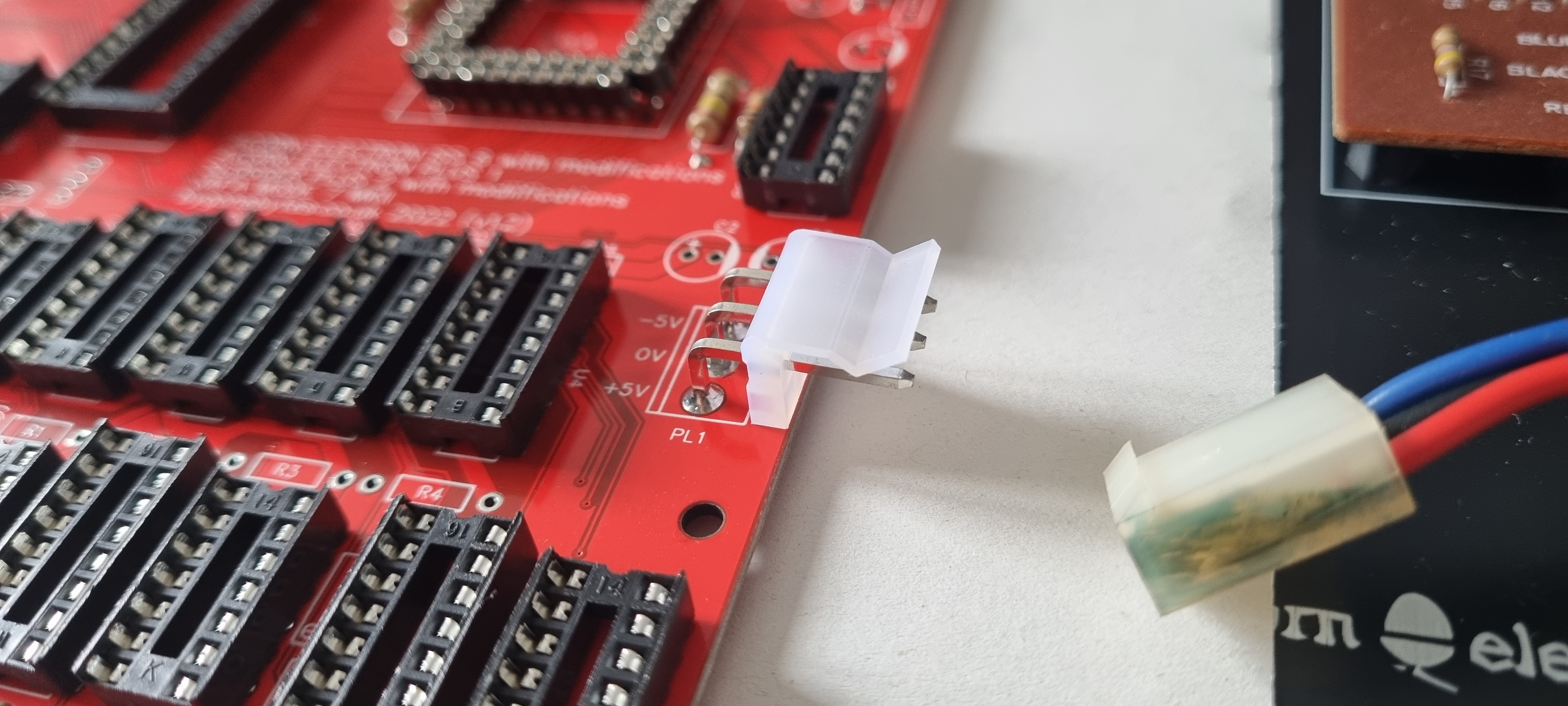
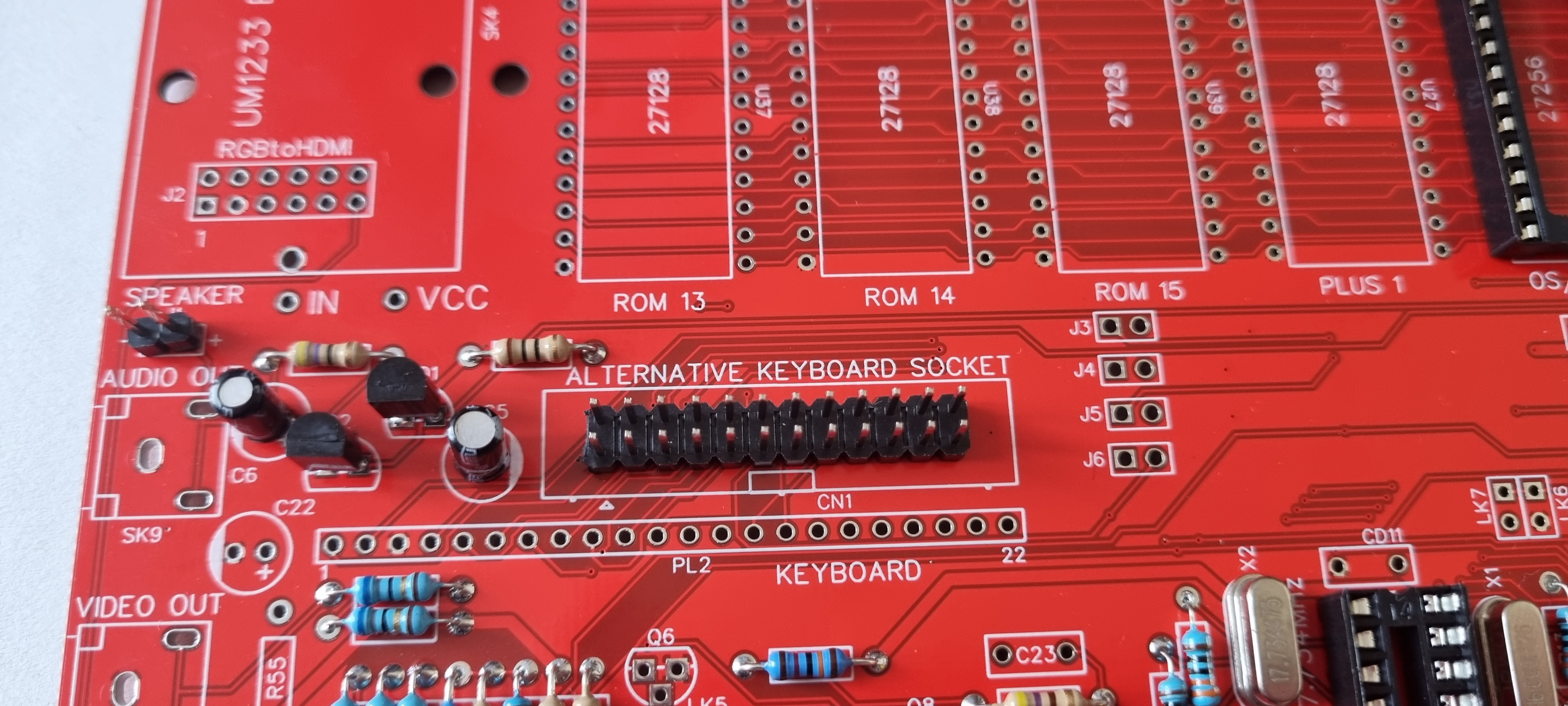
and the power connector, the keyboard socket and sound stage.
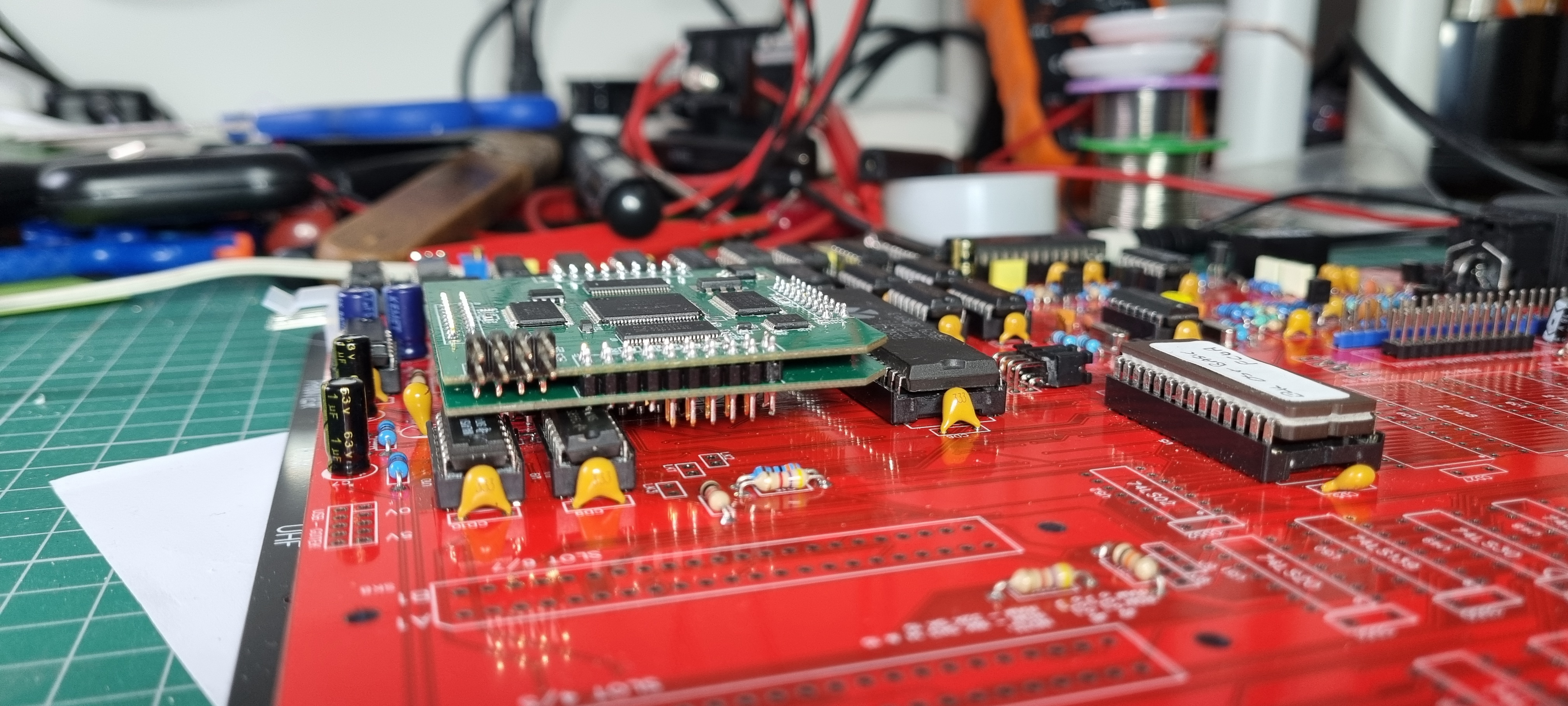
I'll add a few more capacitors then I'll stop here until the new ULA is available so I can check the height of links etc. anything that may end up under the ULA daughter board.
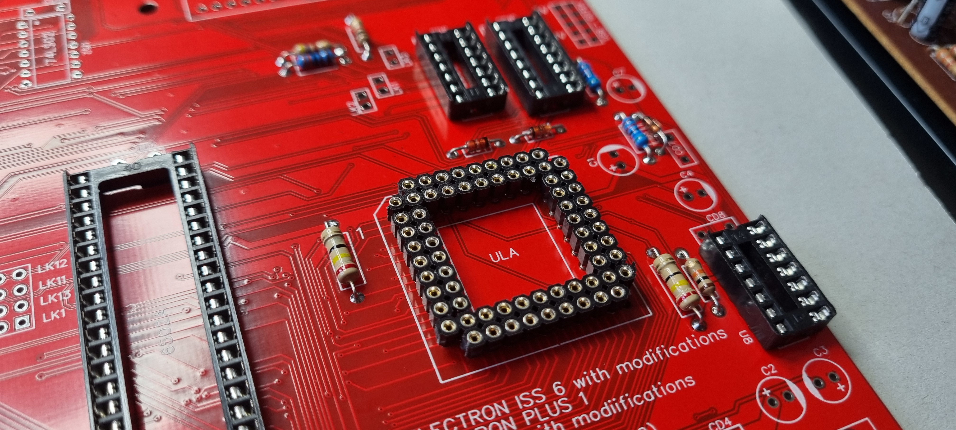
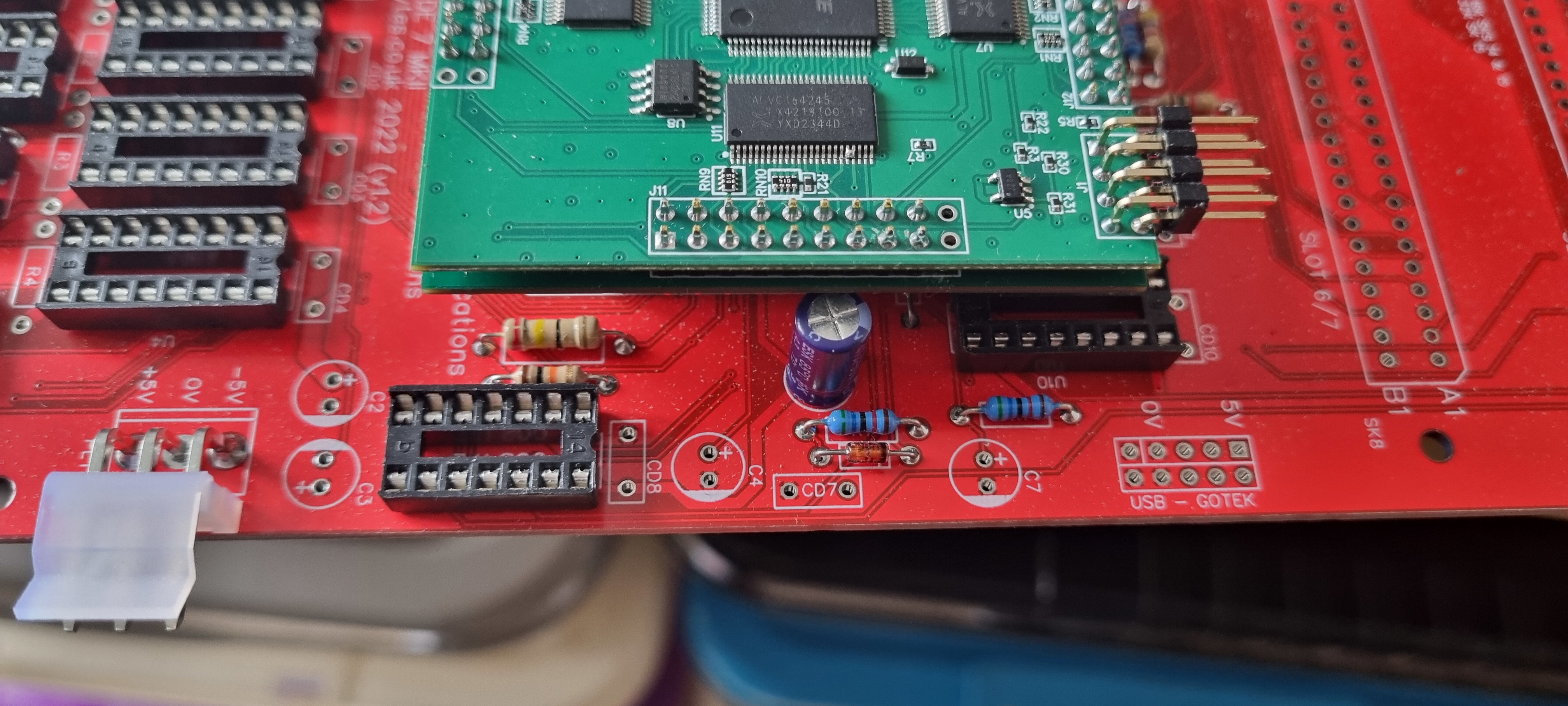
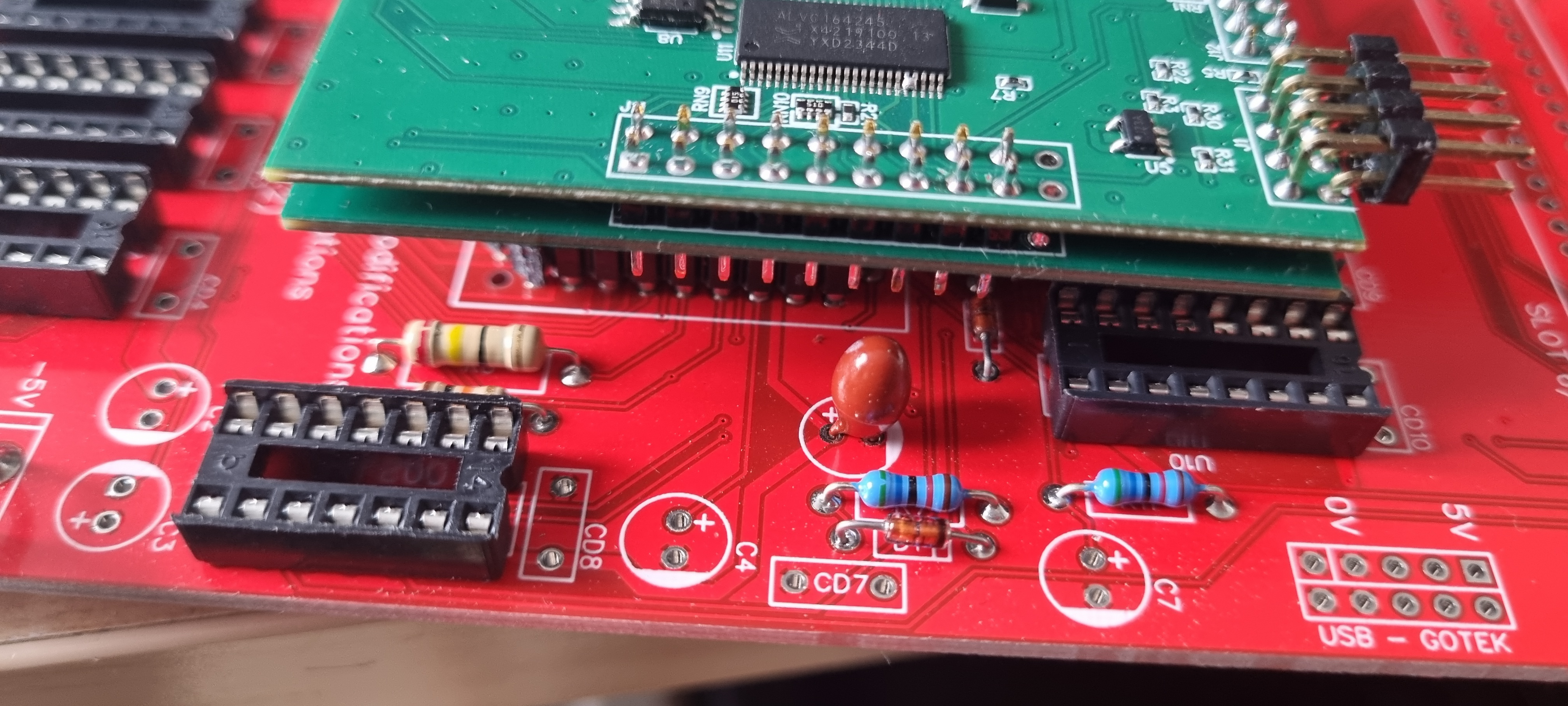
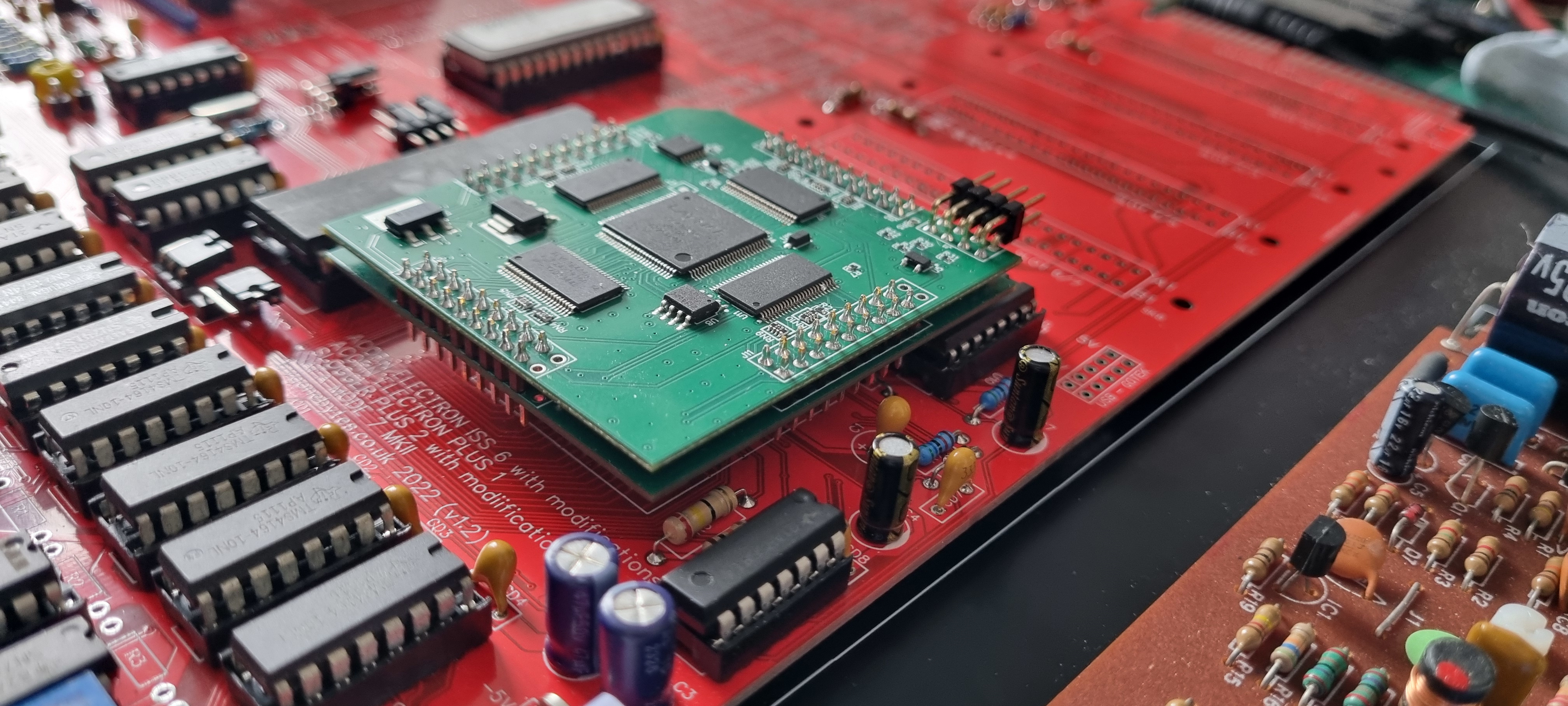
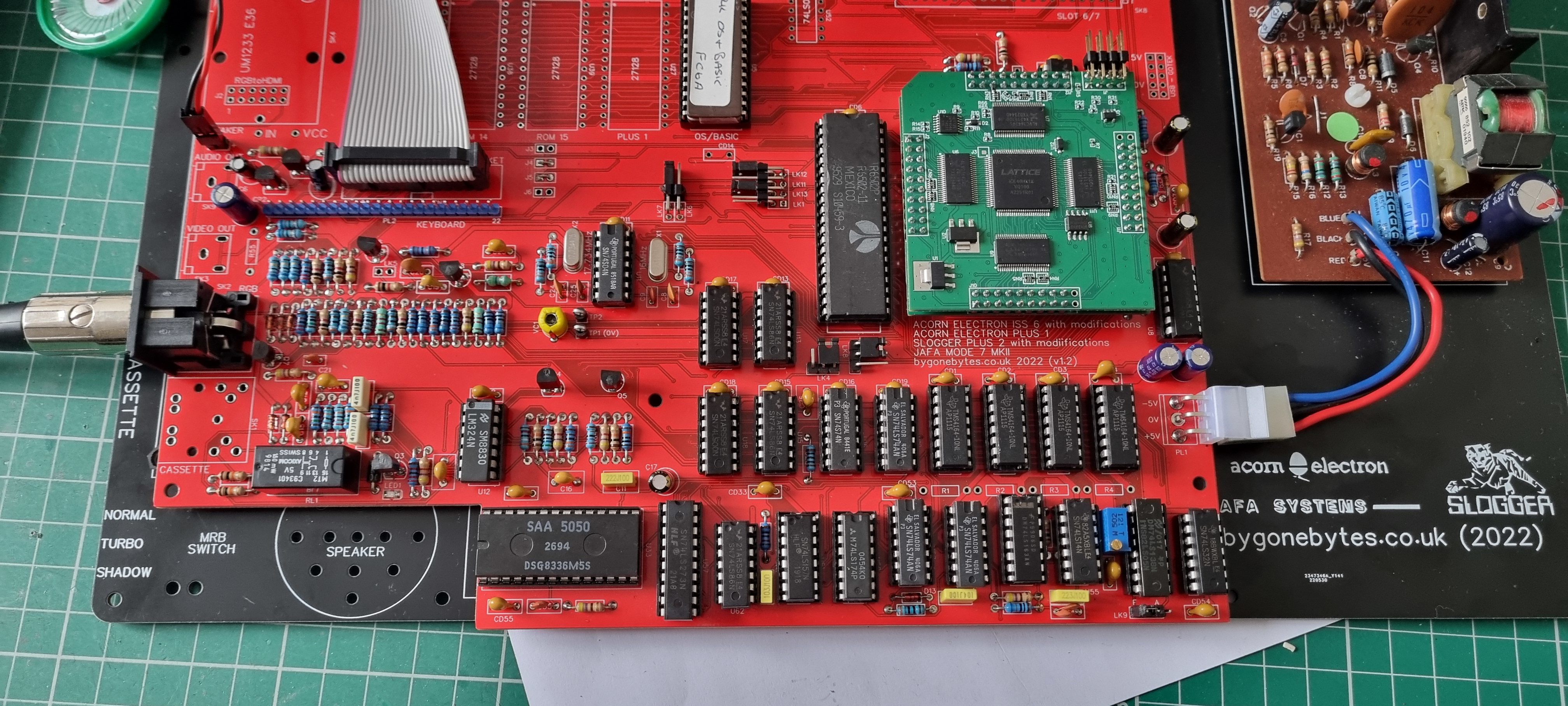
The new ULA arrived and sitting it on the socket I checked the component heights surrounding the ULA to ensure I installed suitable parts. Only one capacitor required to be changed from its usual part - an electrolytic capacitor. Looking at the original issue 6 drawing it should have been a tantalum capacitor all along..
Now to start testing. I removed the ULA and checked the 5V supply and that the oscillators were running. I didn't bother to check the frequency, I just used a logic probe to check they were switching. Before risking the new ULA I used a spare original to check all is ok. it wasn't of course! I had one faulty RAM IC - it's always a hit & miss when buying 'new' RAM chips. Replacing that I got the sign-on beep and the Acorn banner on the screen.
Now that all the IC's are plugged in I noticed the new ULA wouldn't sit right down into it's socket as all the IC's are now in sockets. I simply trimmed a few pins on one of the the new ULA's headers and it seated perfectly.
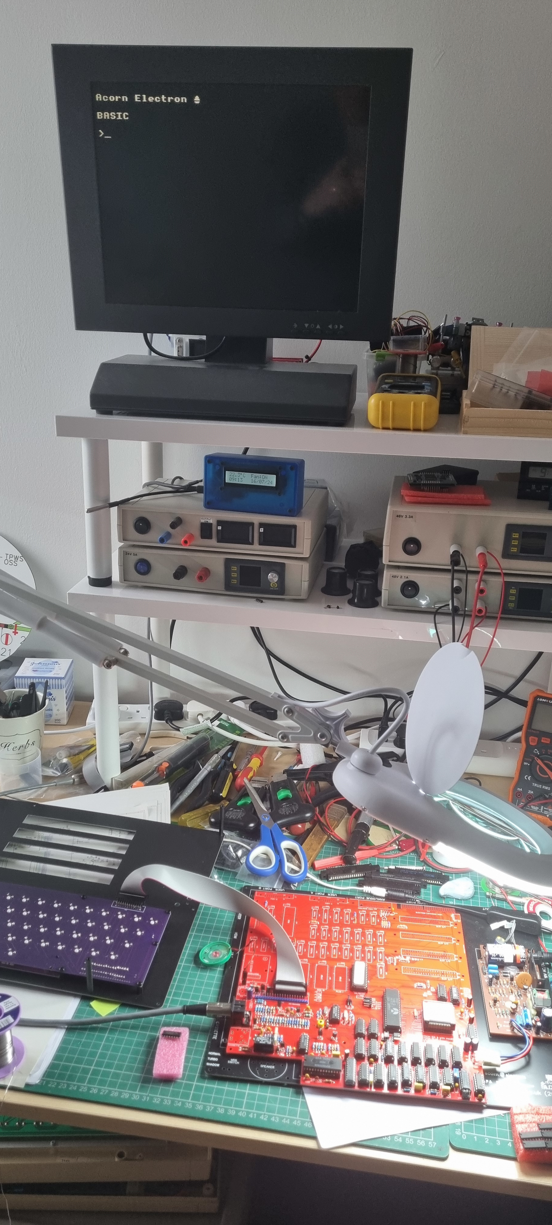
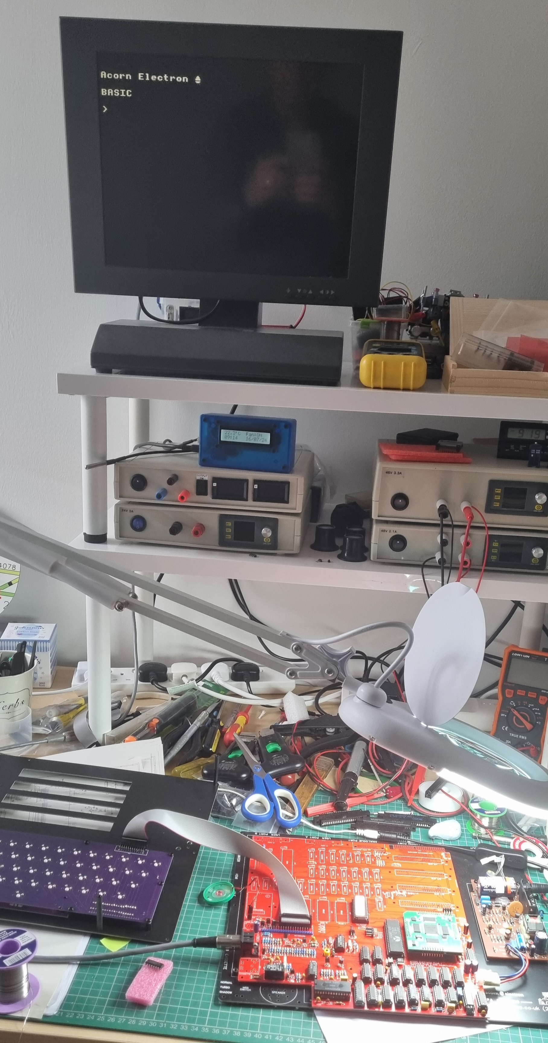
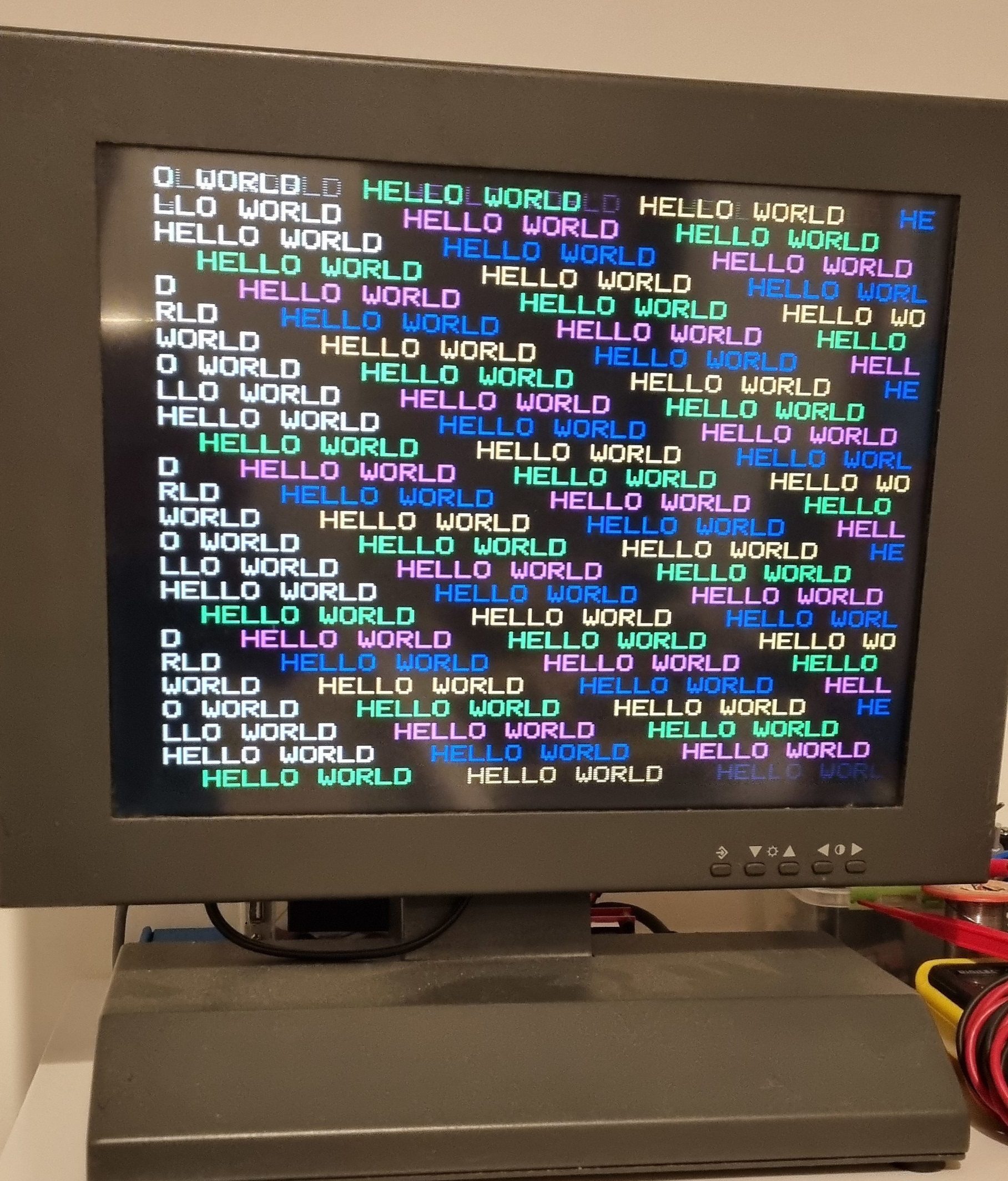
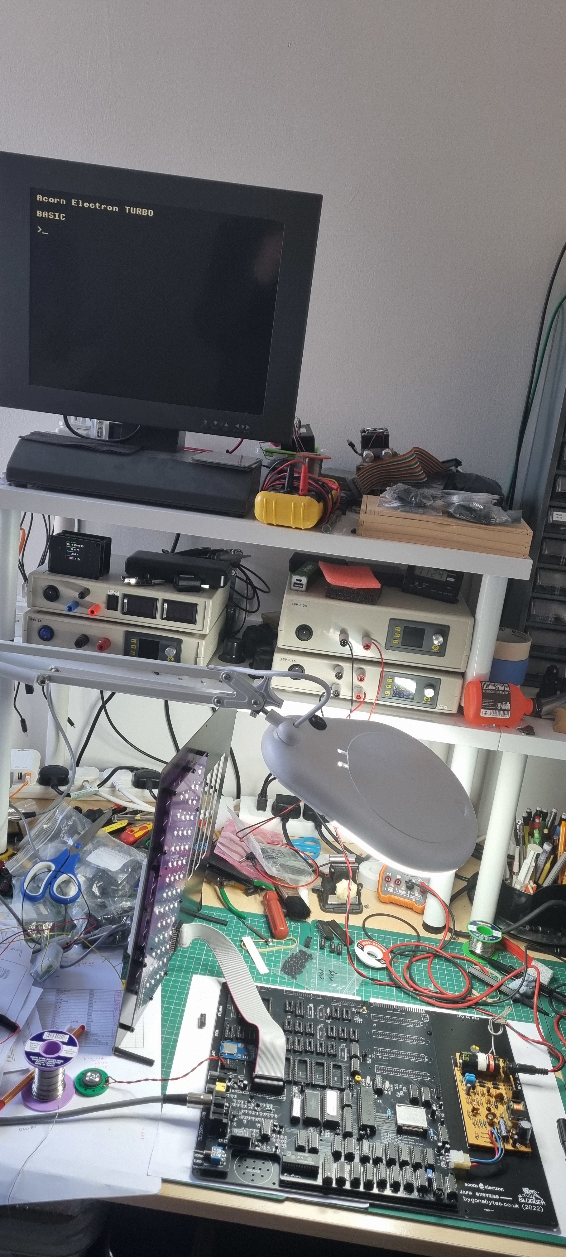
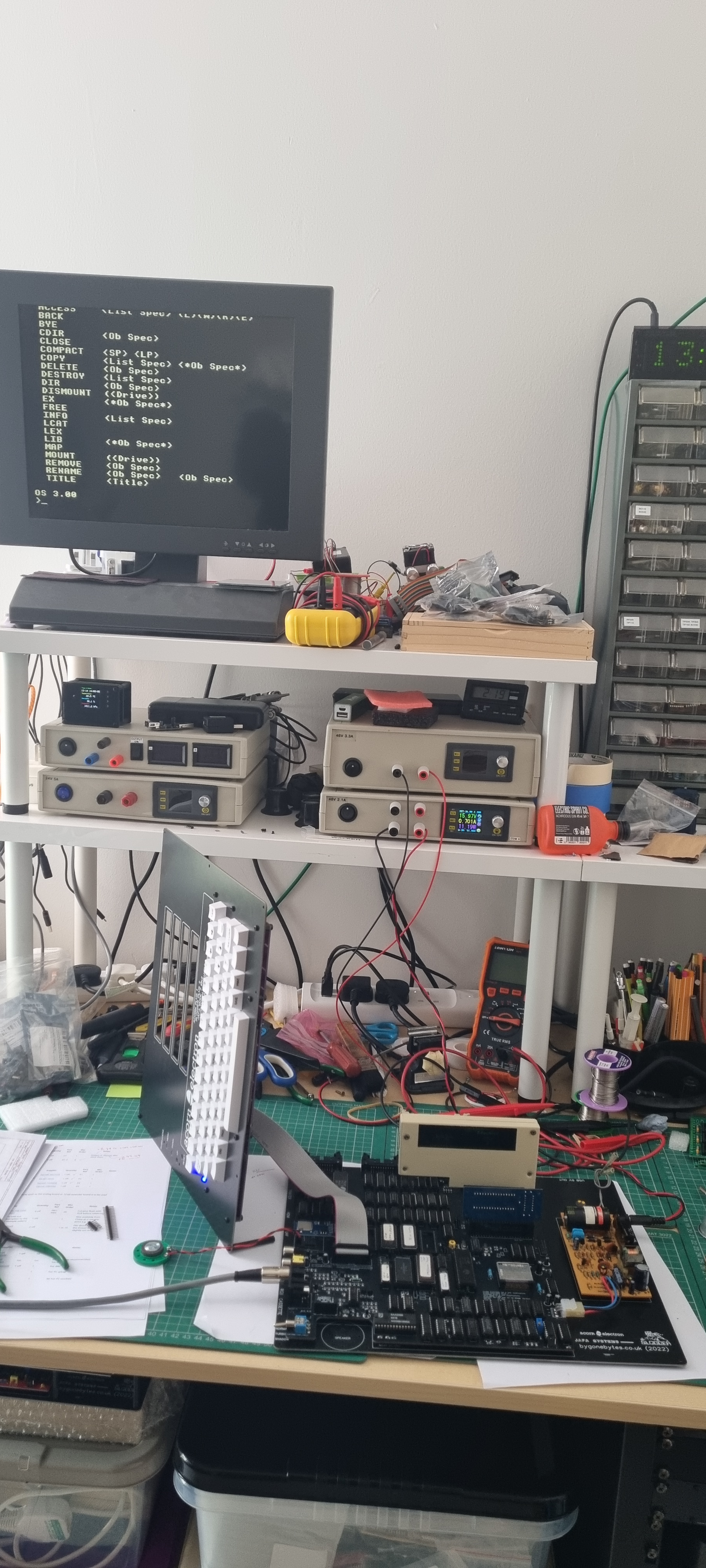
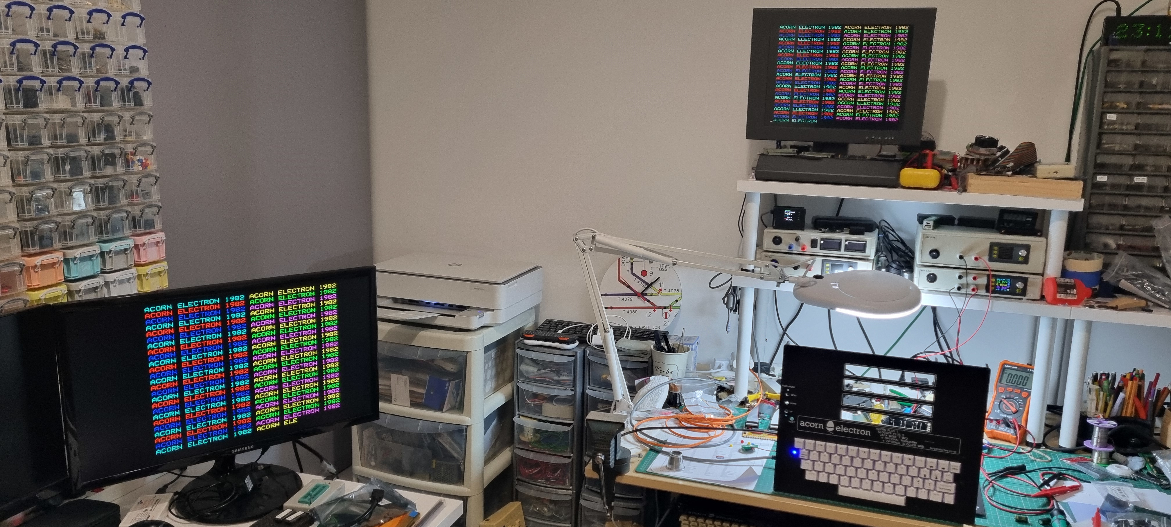
The time has arrived and with great anticipation I switched it on. Perfect, so I did the obligatory 'Hello World'.
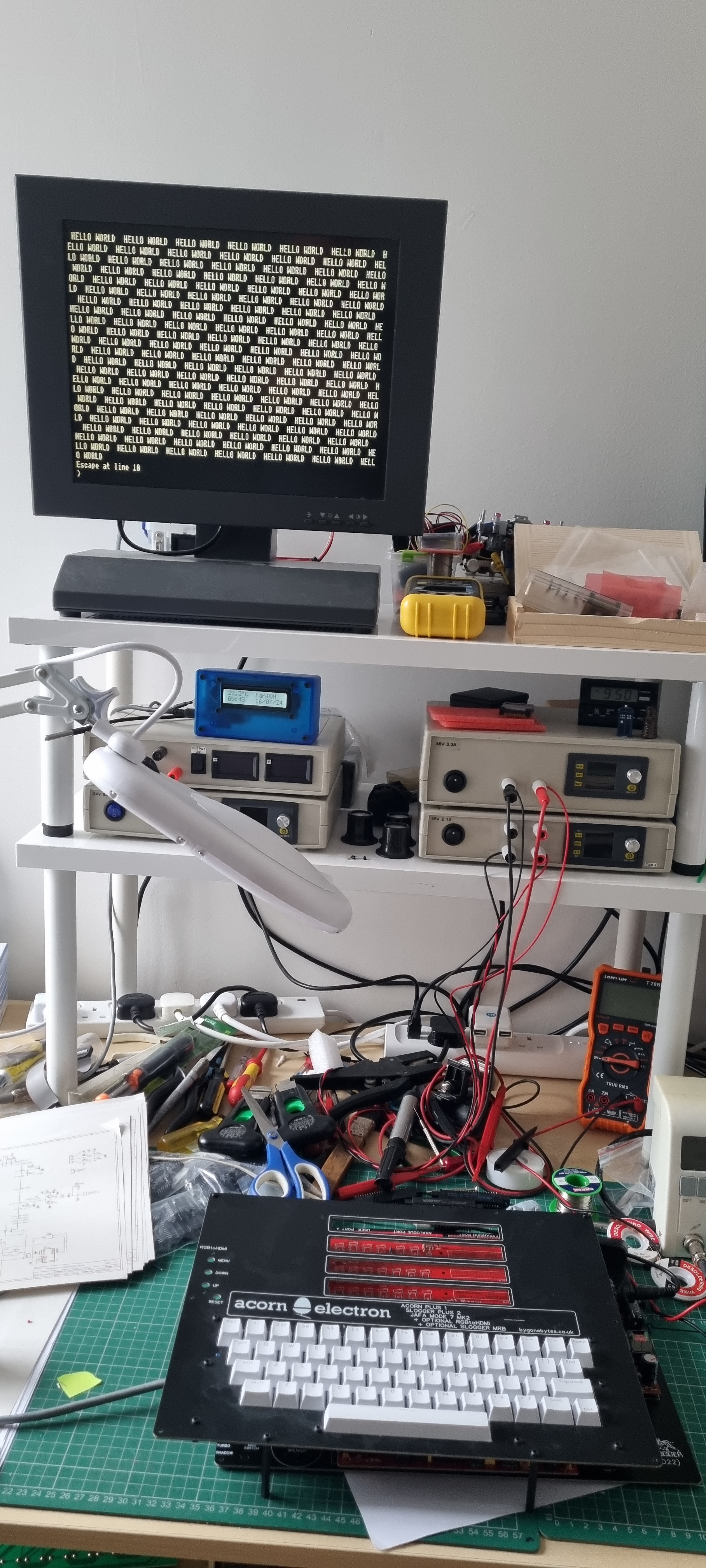
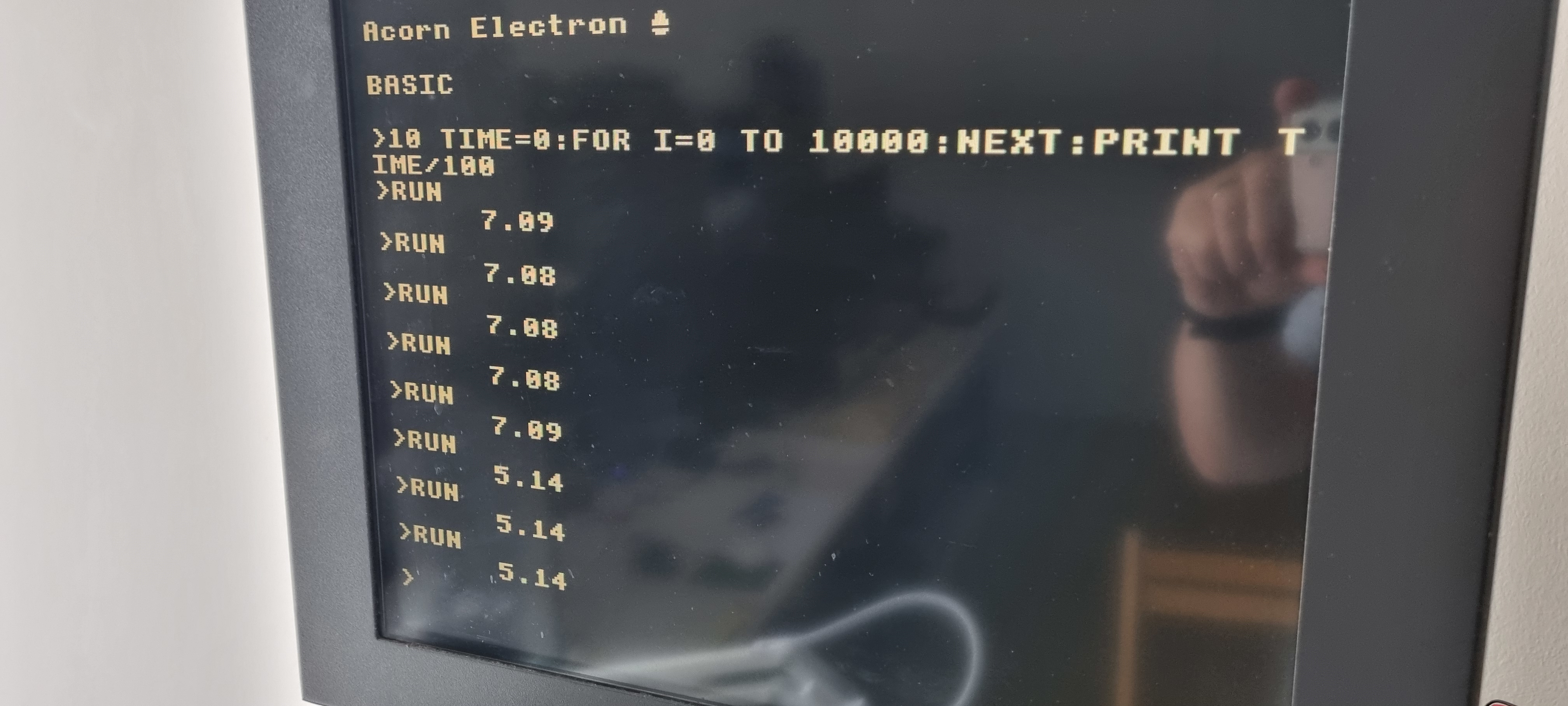
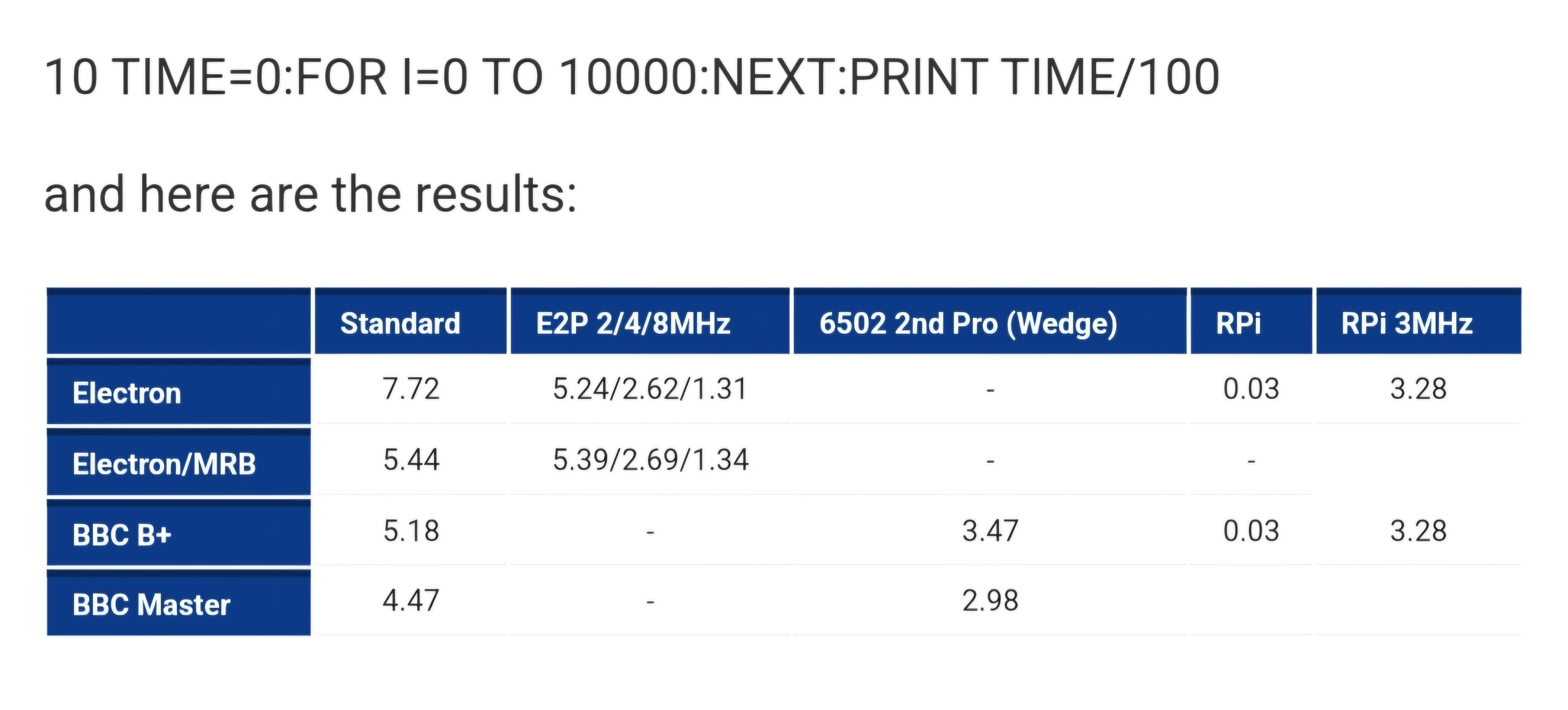
Four or five years ago I did some simple benchmarks on various configurations of Electrons and BBC's so it came to mind to see how this one performs.. Slightly faster that an original Electron and in turbo mode a bit faster that the Slogger MRB.
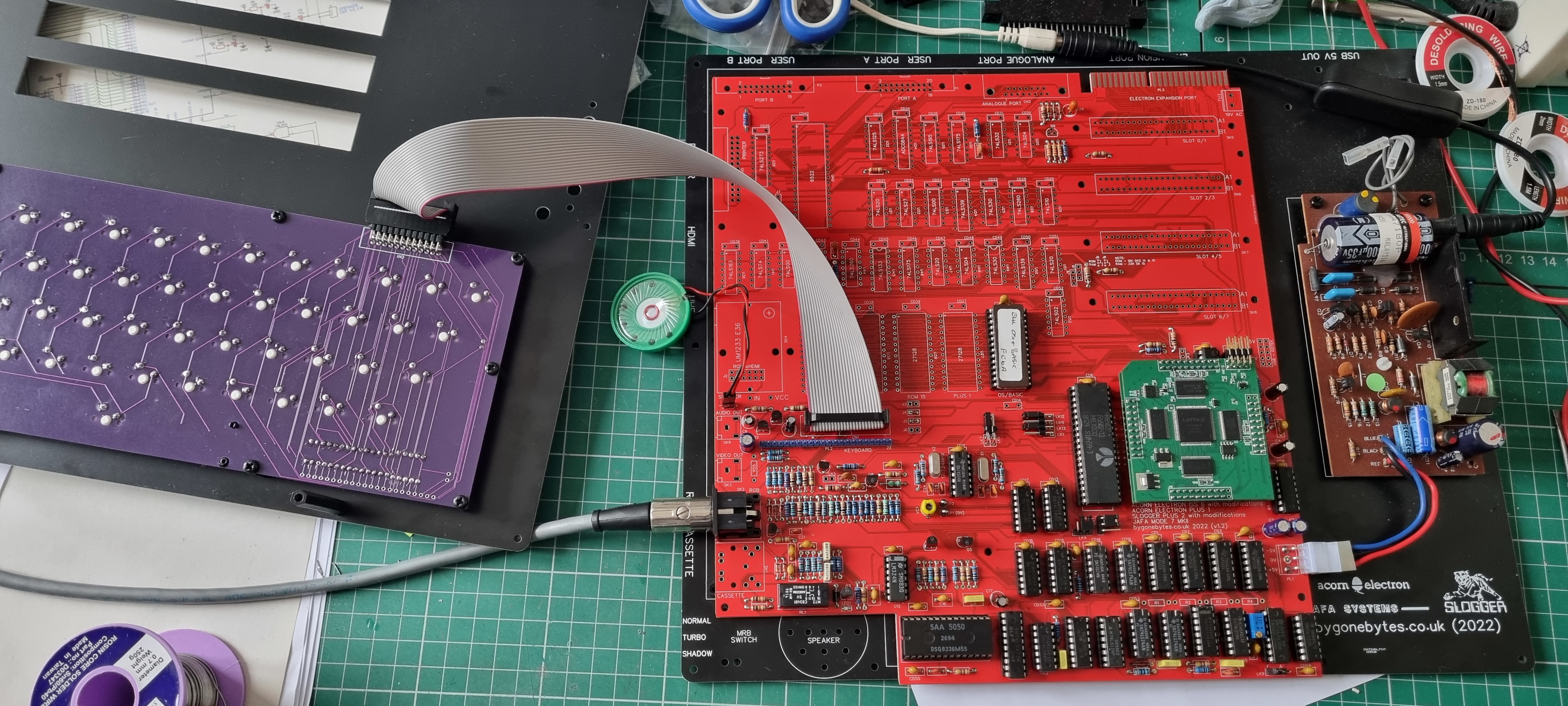
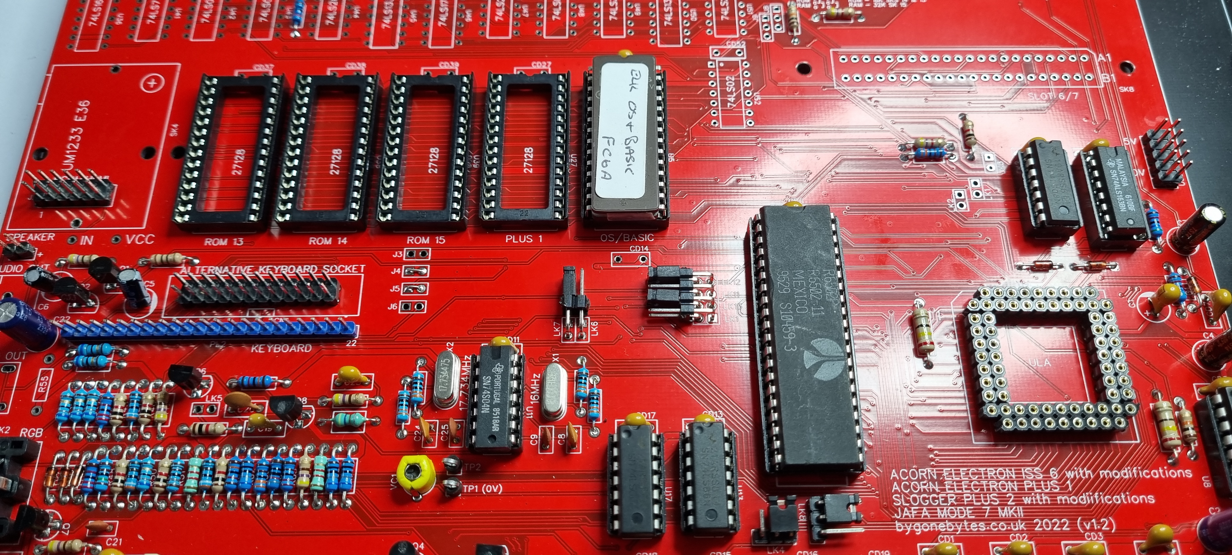
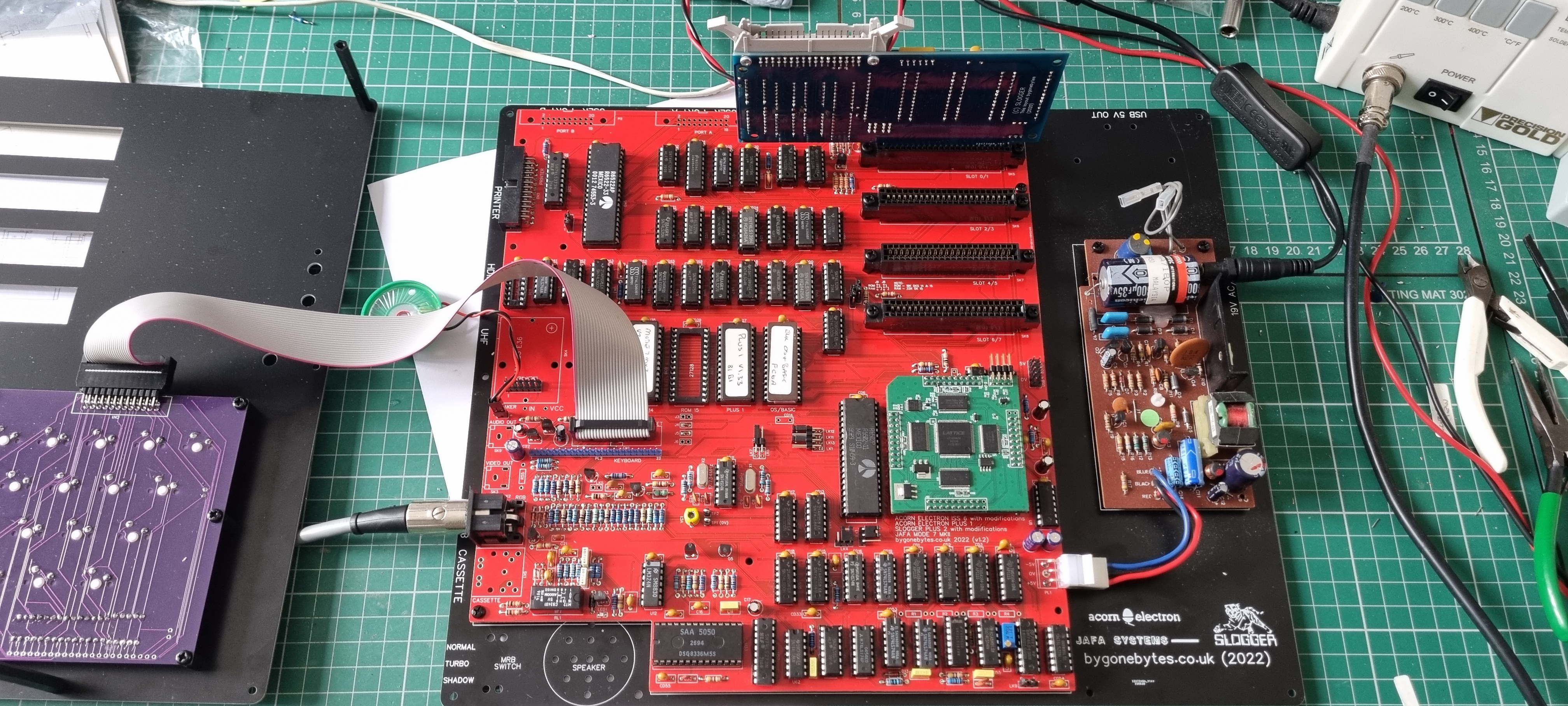
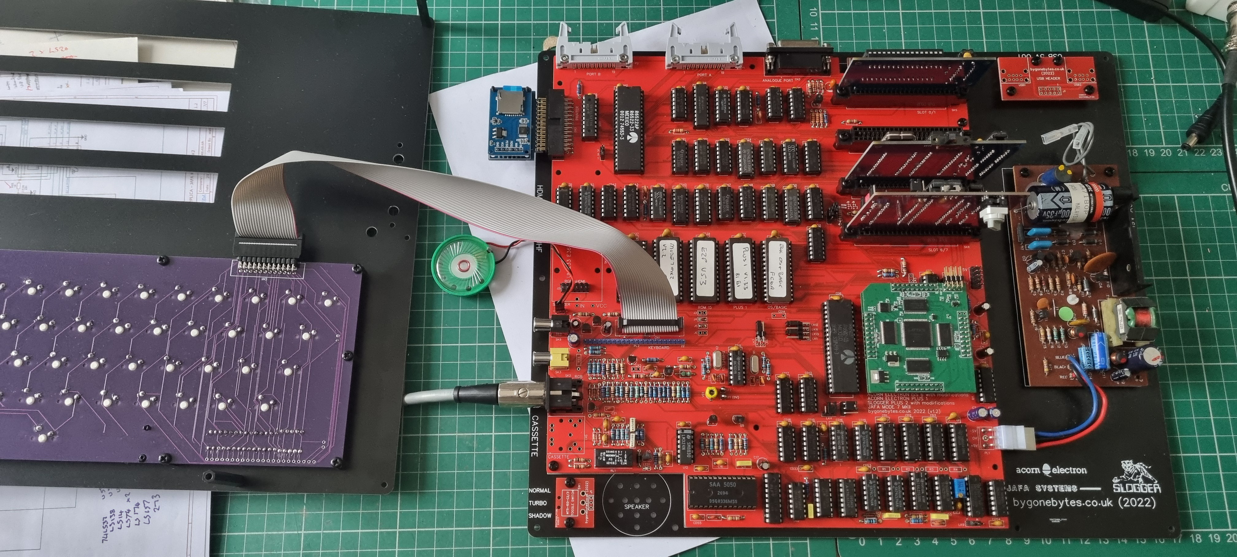
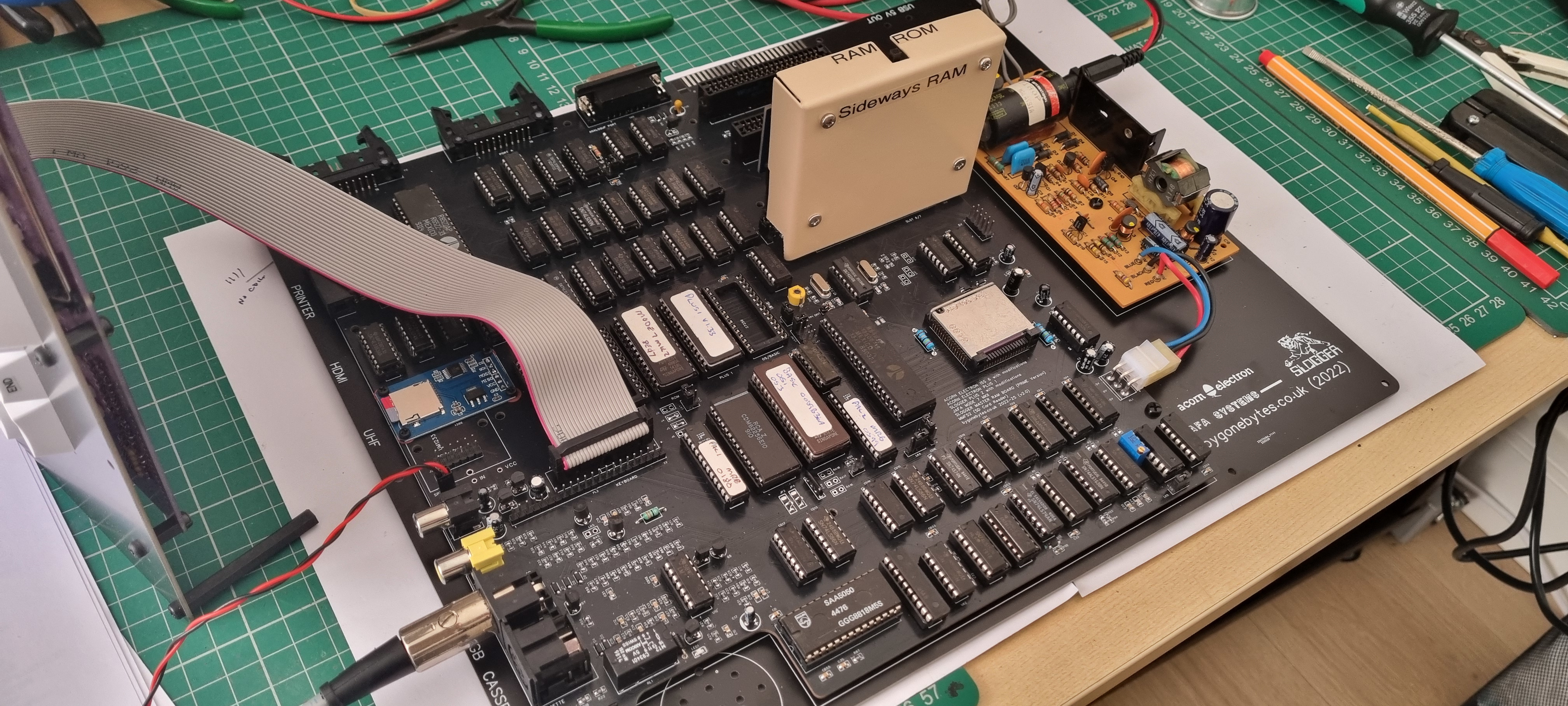
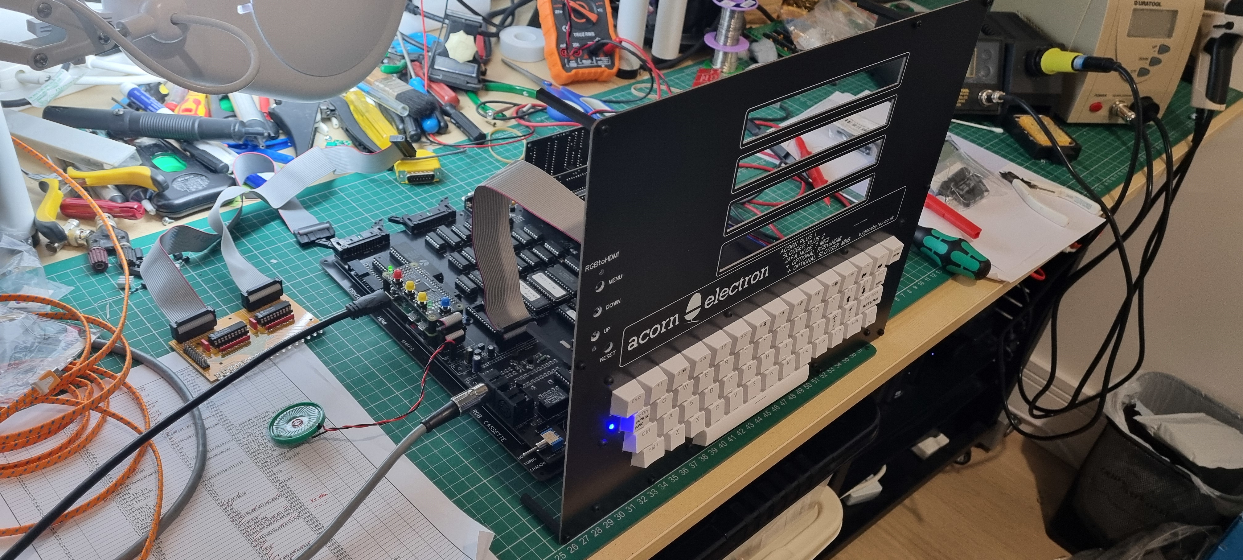
After that little success I went on to build the rest of the board, IC sockets first then decoupling capacitors and lastly insert all the IC's. At the moment I'm one IC short and that's the 74ALS163 which is used in the Mode7 adaptor. I decided to try the 74LS163 from the Plus 2 circuit (no spares) as it only affects the Plus 2 user ports which I can test later. This allows me to power up and see what works.
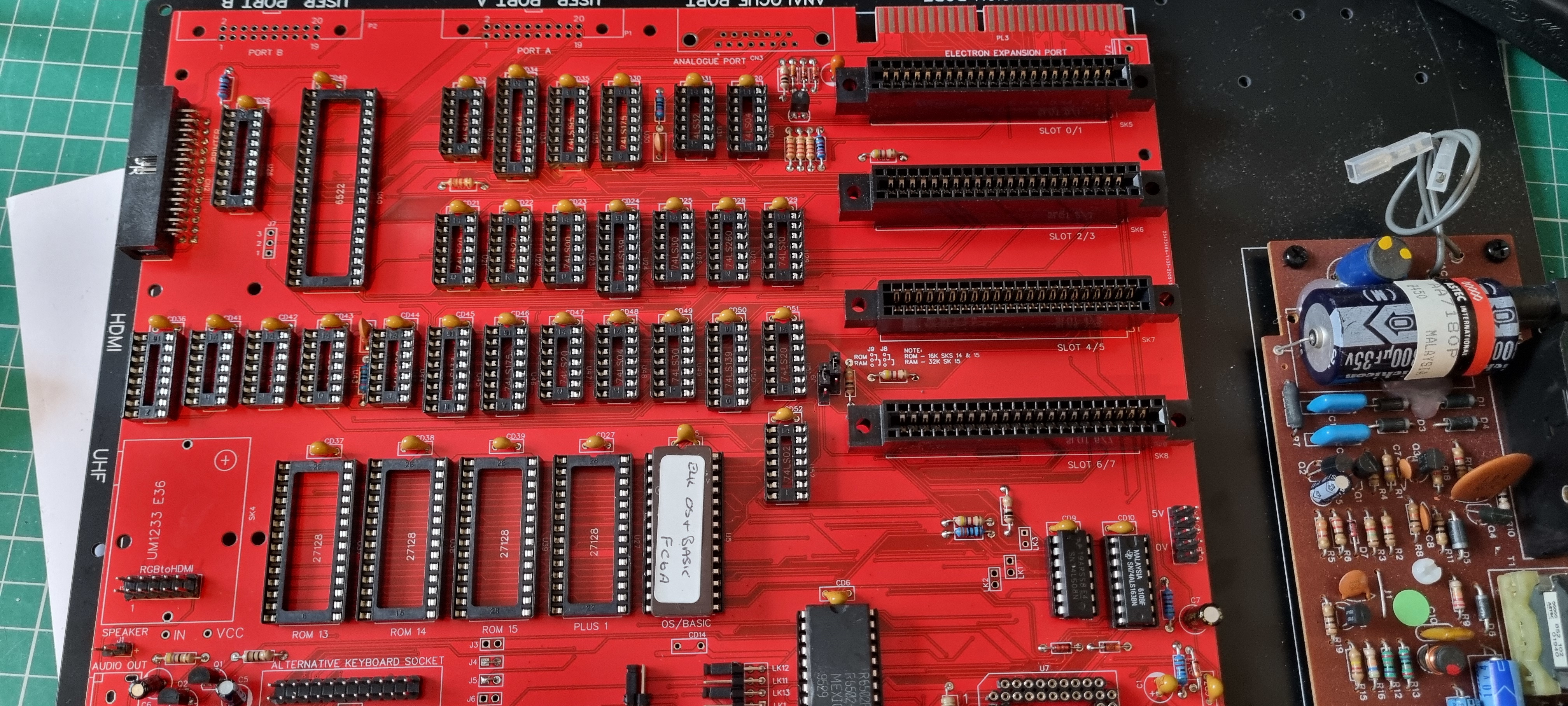
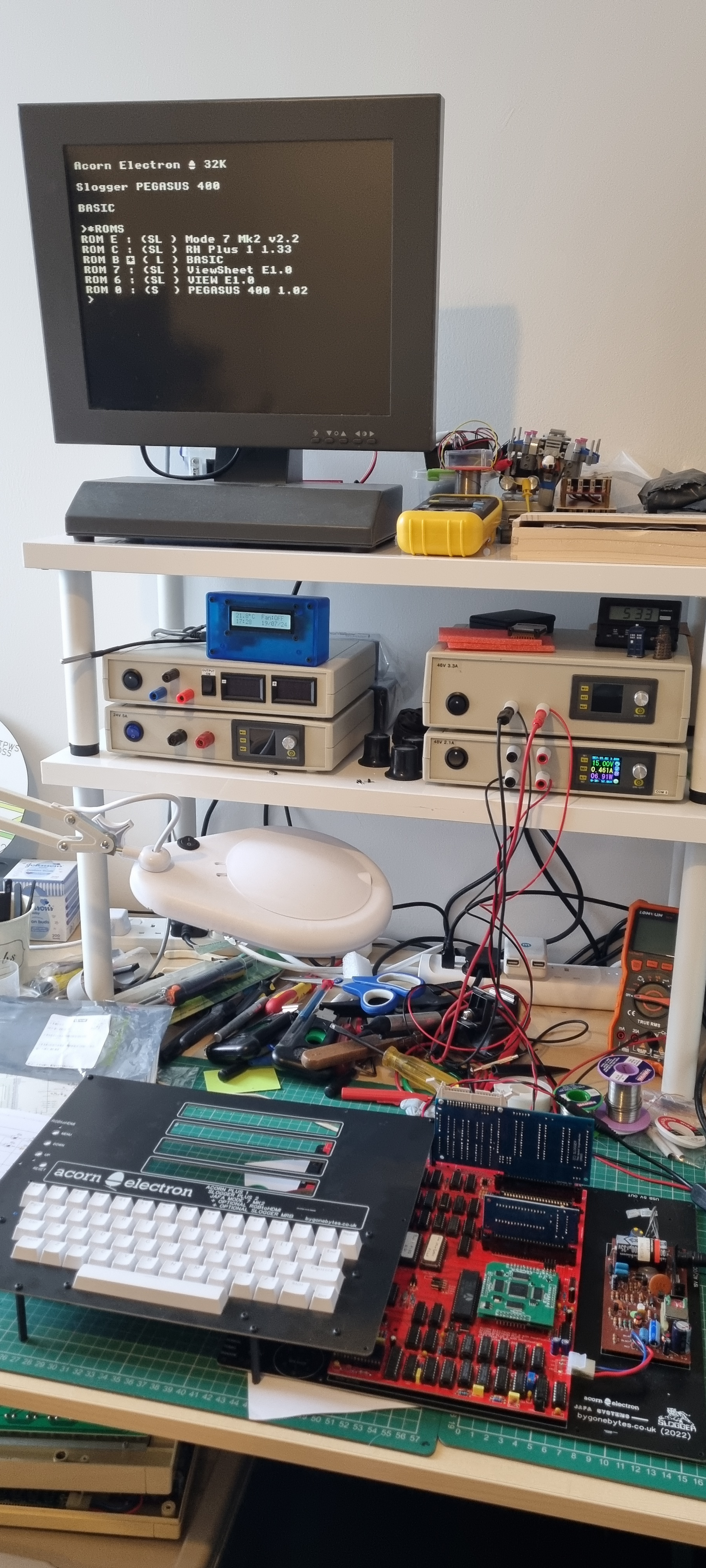
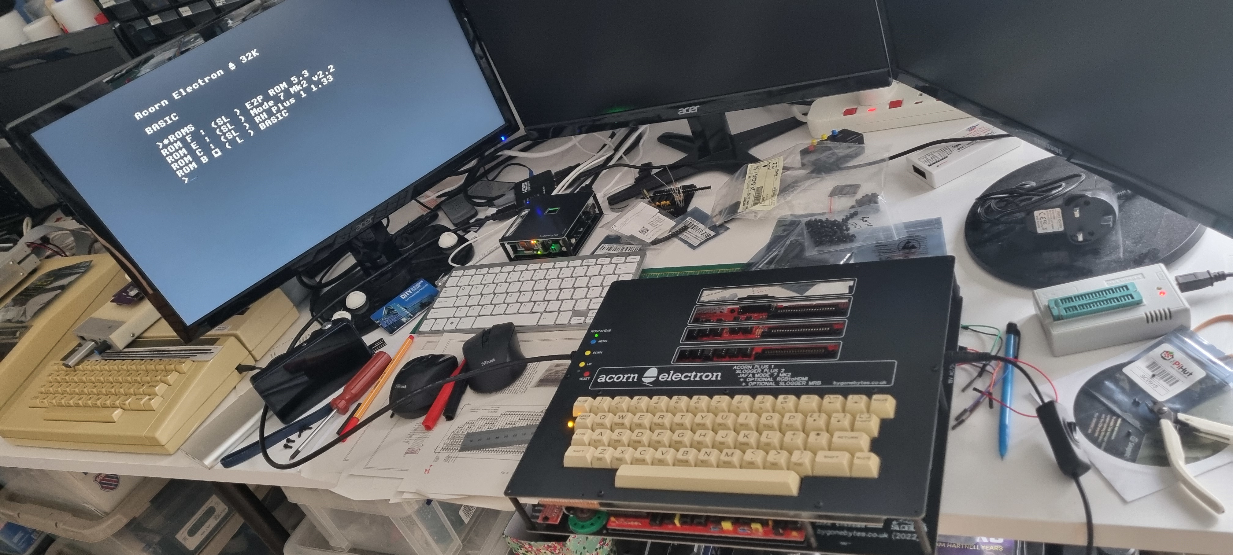
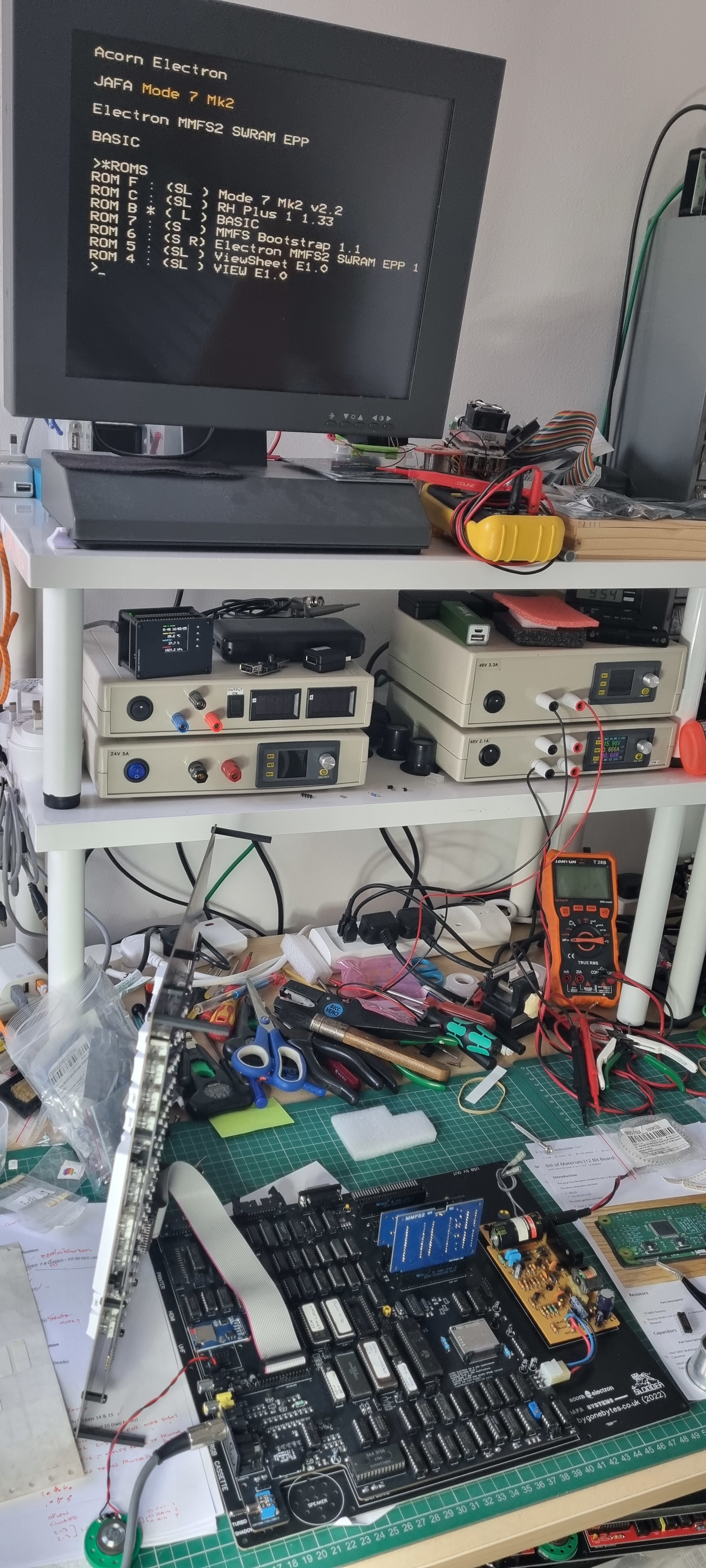
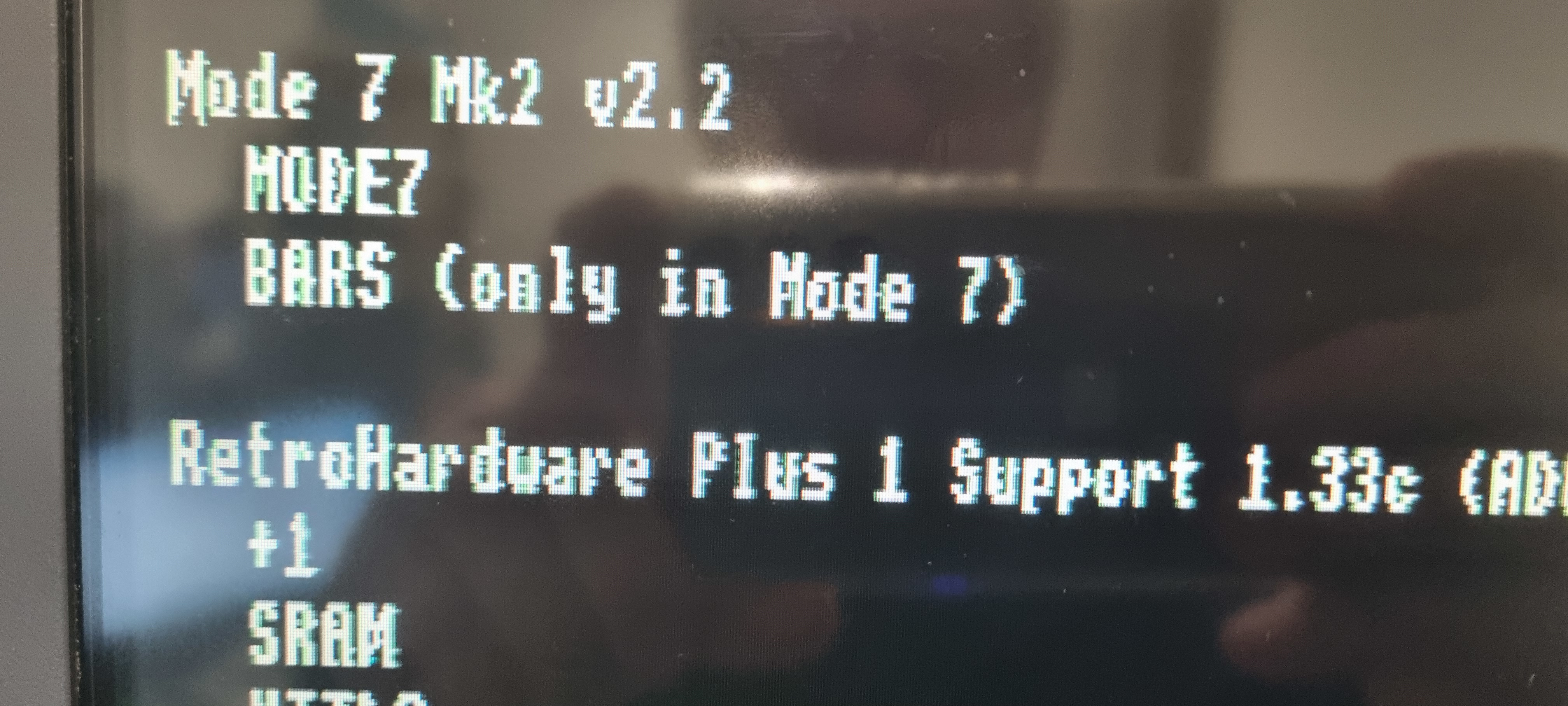
And immediately I noticed the start up banner for the Plus 1 ROM is missing. So trying *H. the ROM is present and *ROMS shows all the ROM's are there so the PLUS 1 ROM works OK, it's just the banner not showing. Something to look in to - and I did. The Mode7 MK2 ROM either suppresses the banner or it over writes it - not a problem.
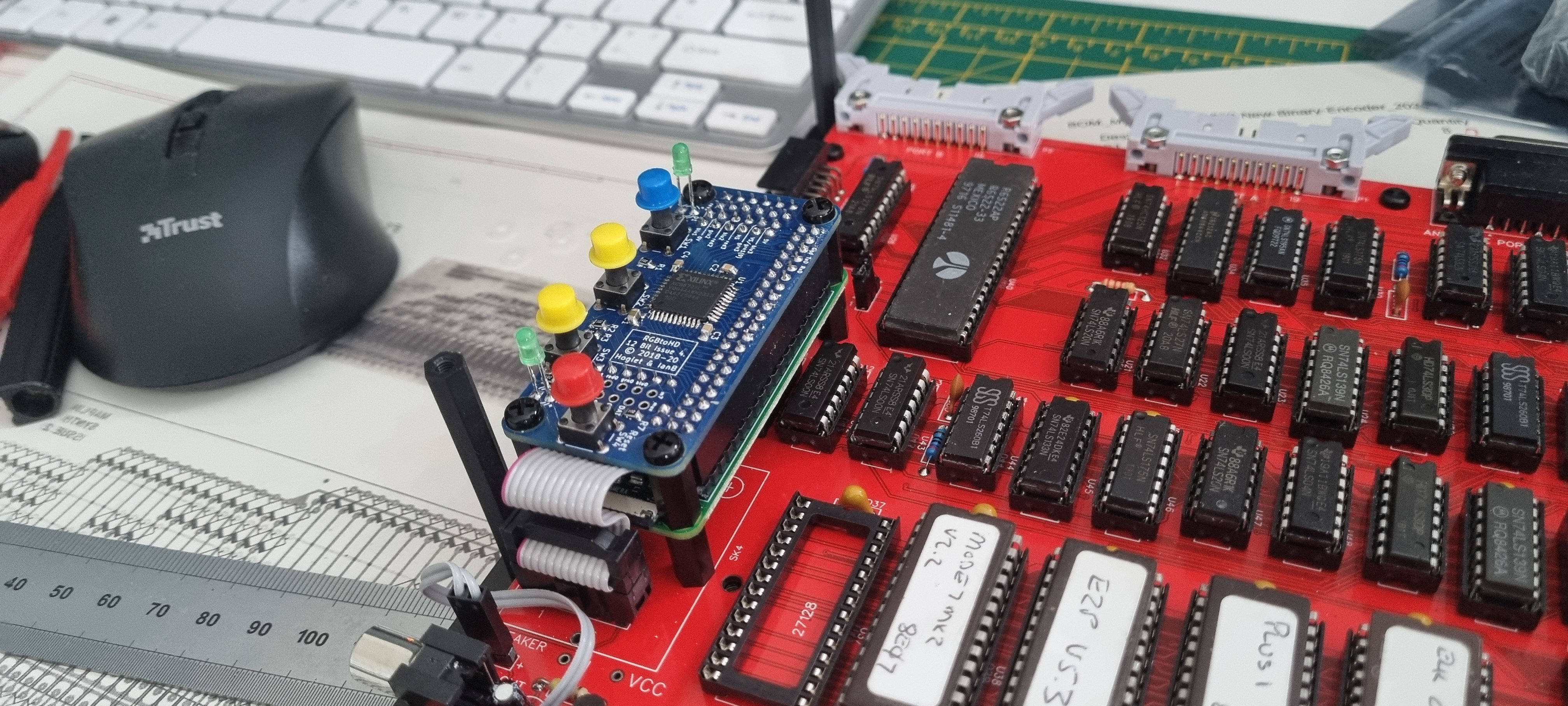
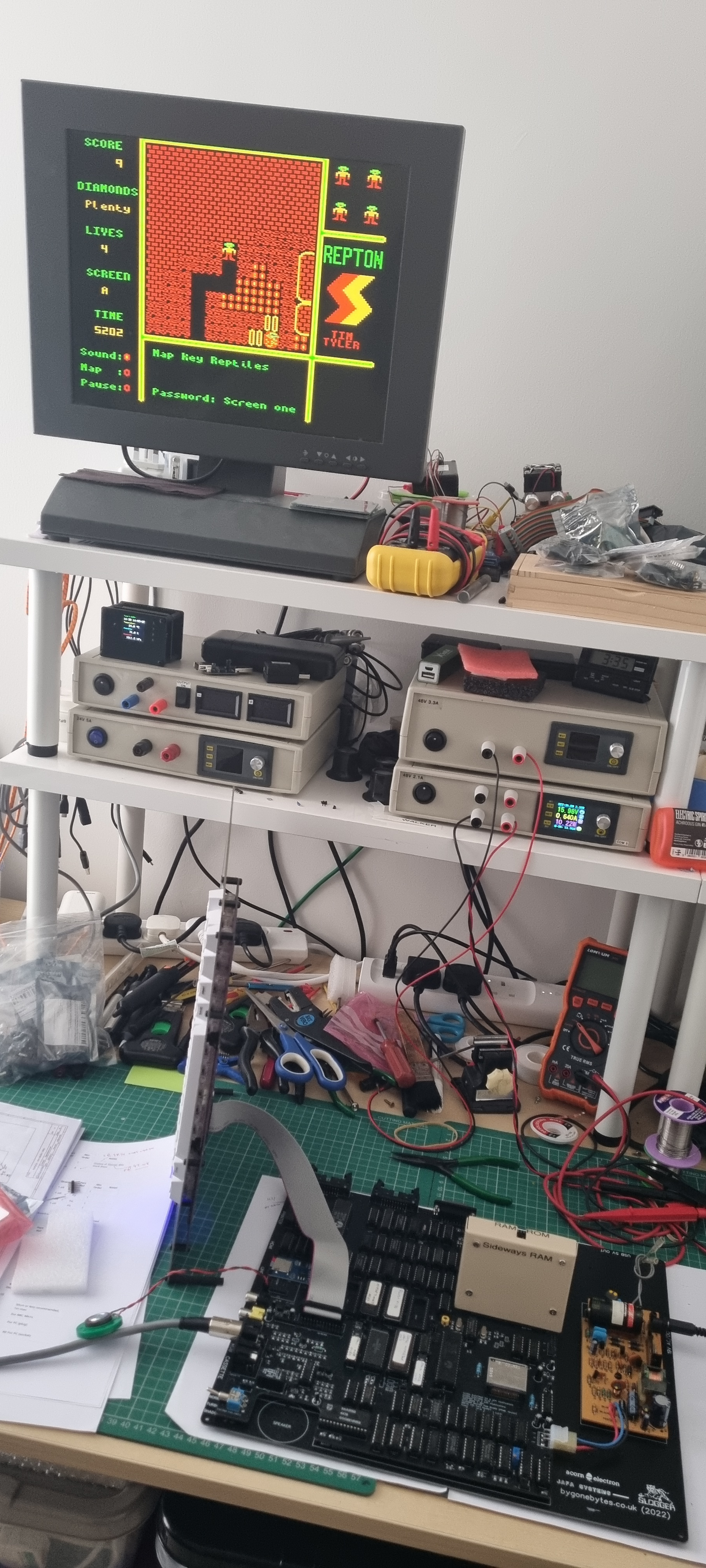
I then plugged in a couple cartridges, the Slogger Pegasus an a ROM cartridge with View and Viewsheet. Interestingly the Pegasus banner is displayed.
To be continued once I receive the 74ALS163...
A little aside:
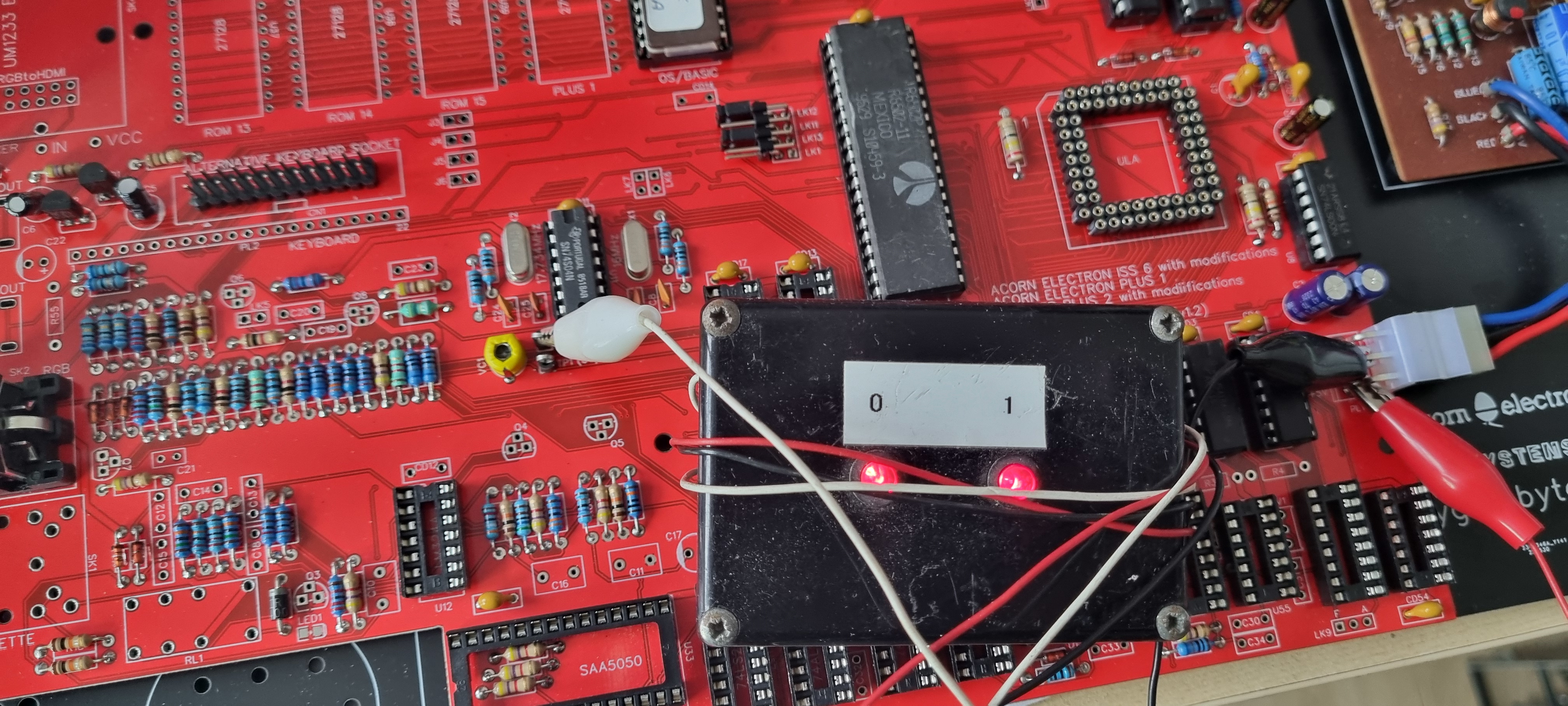
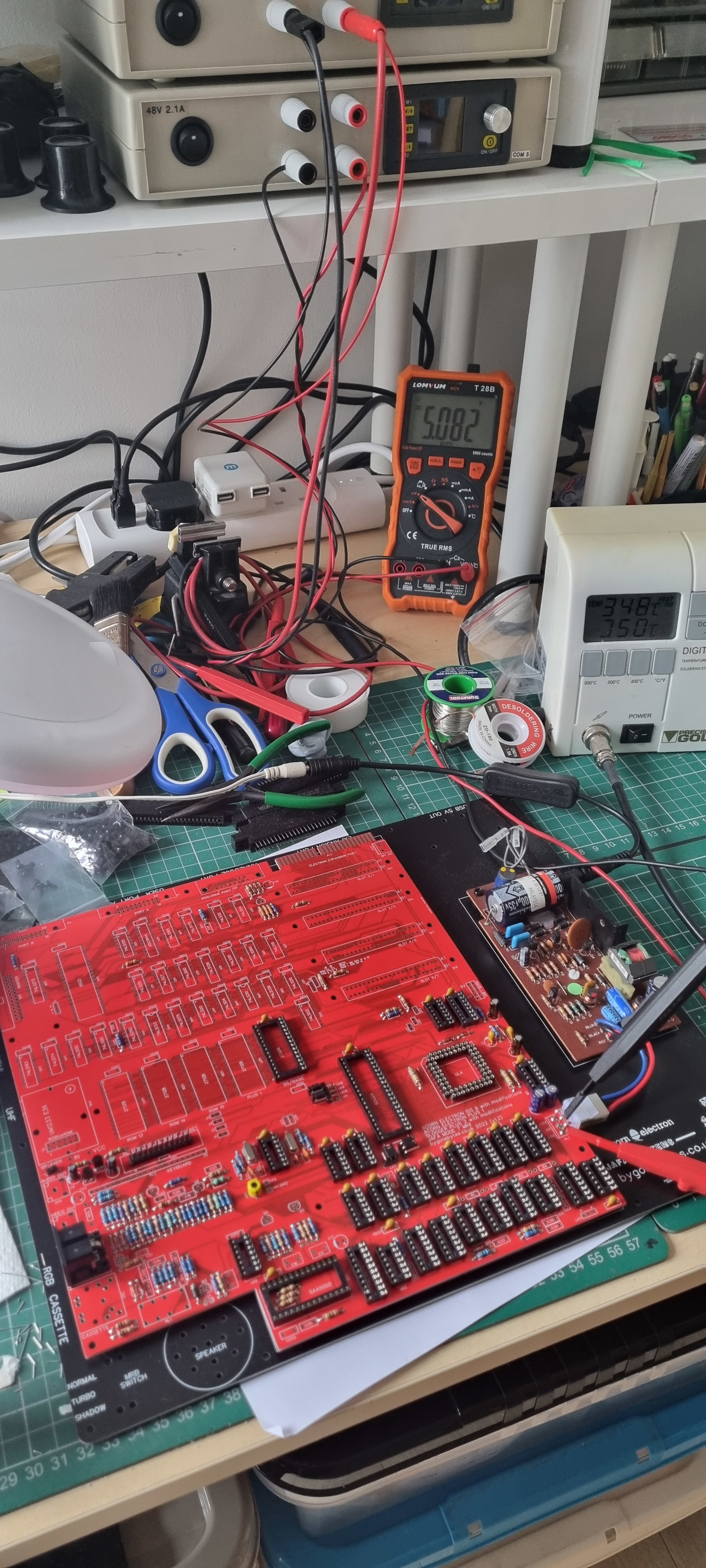
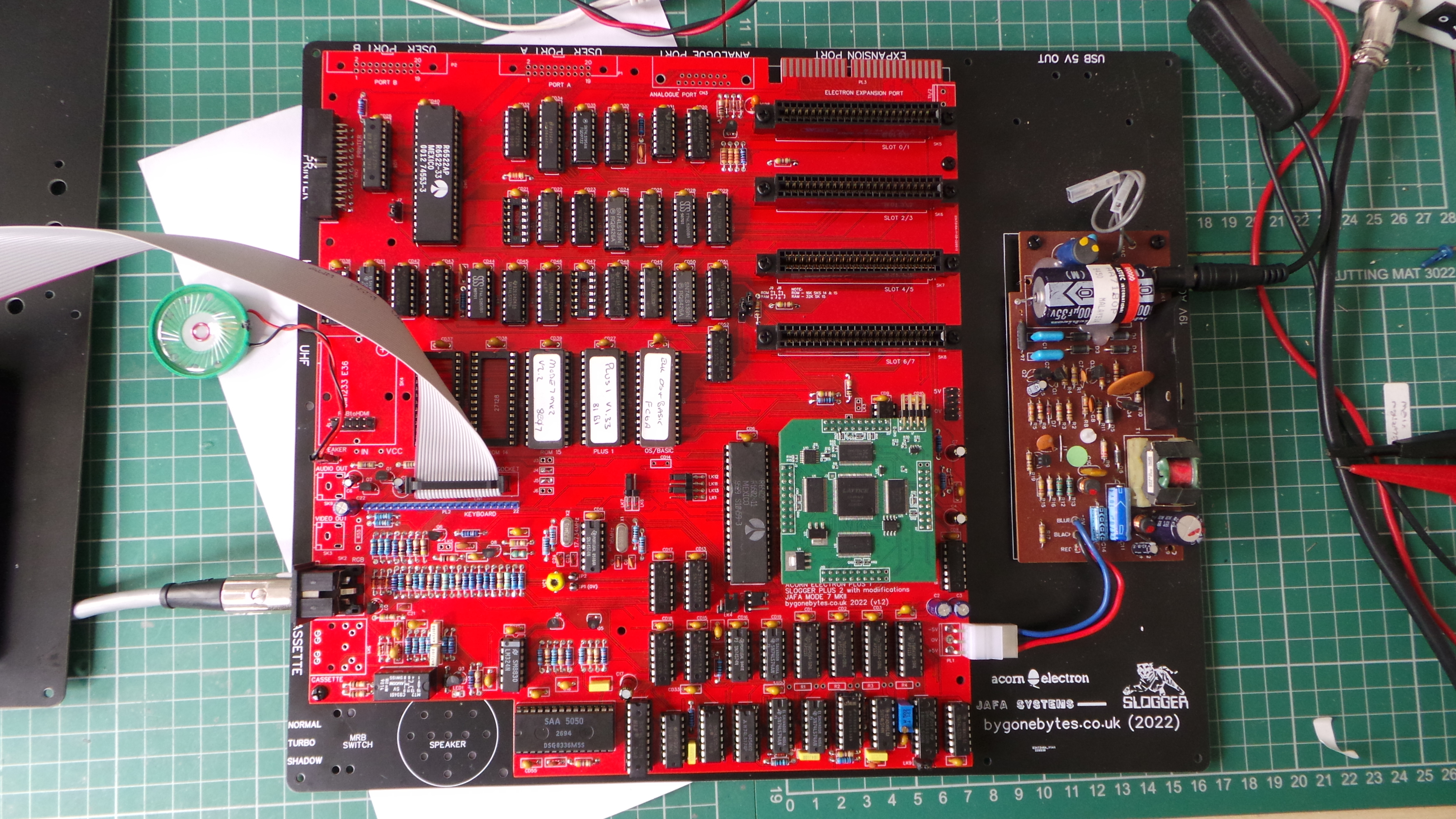
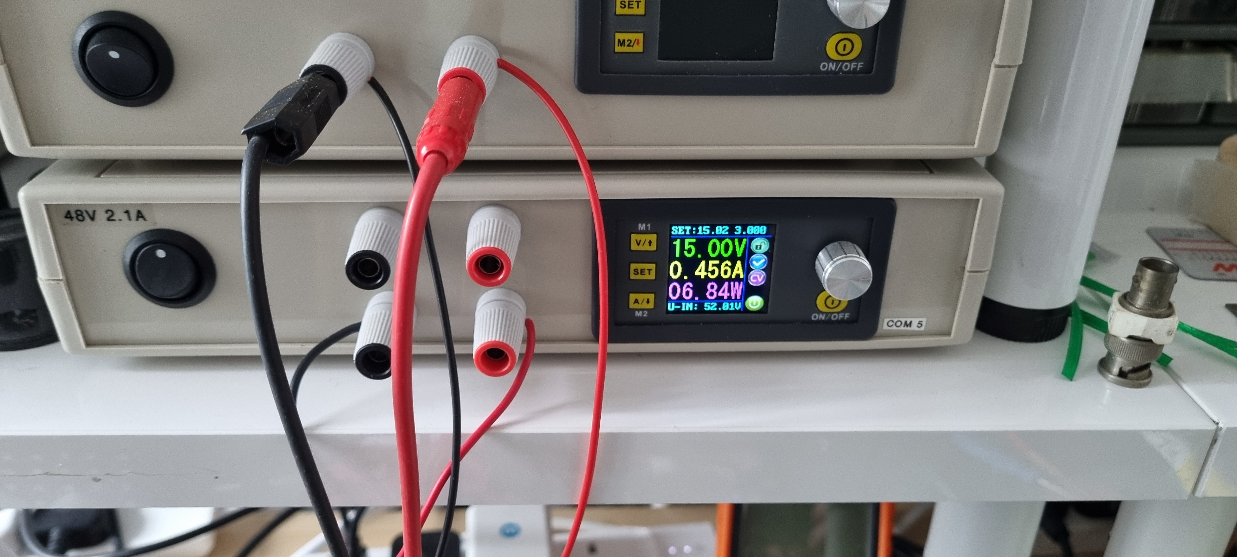
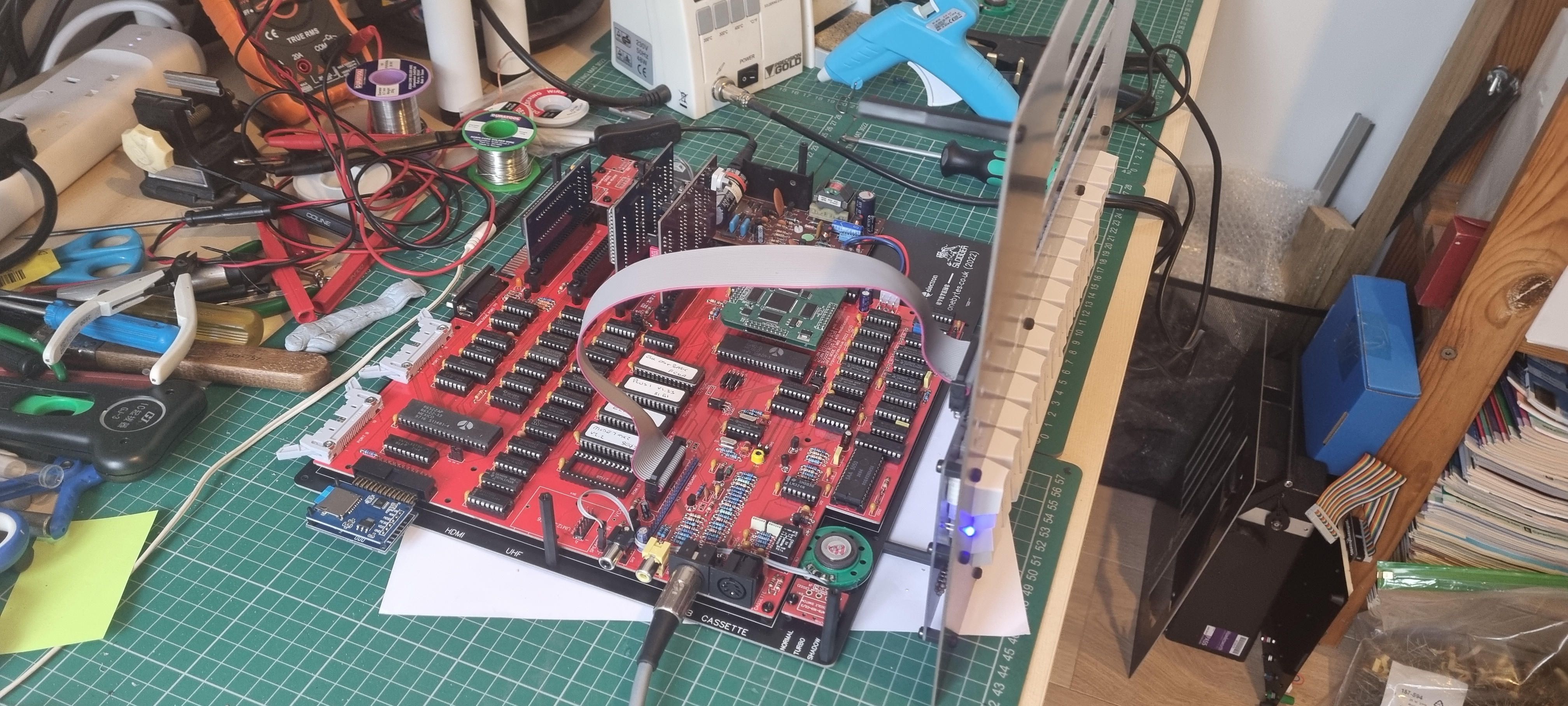
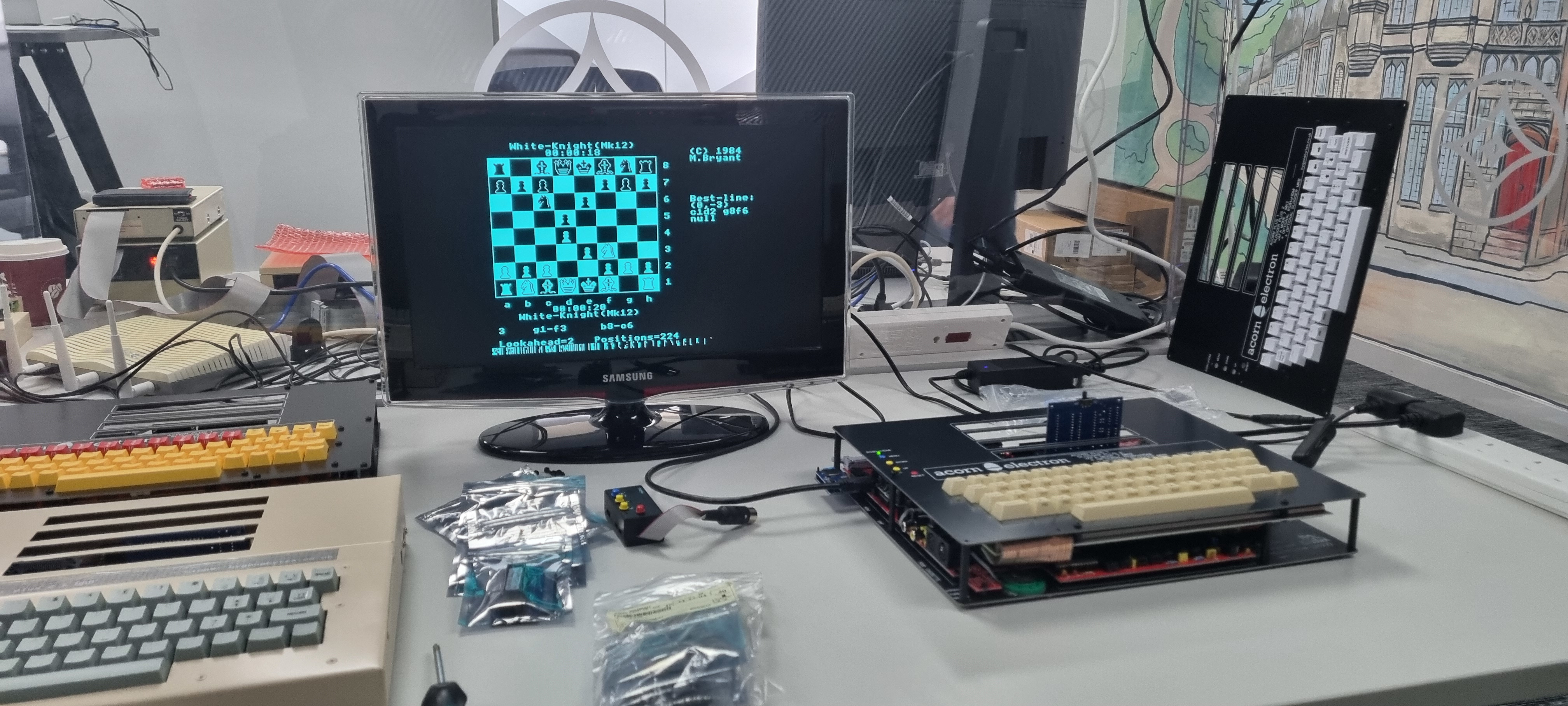
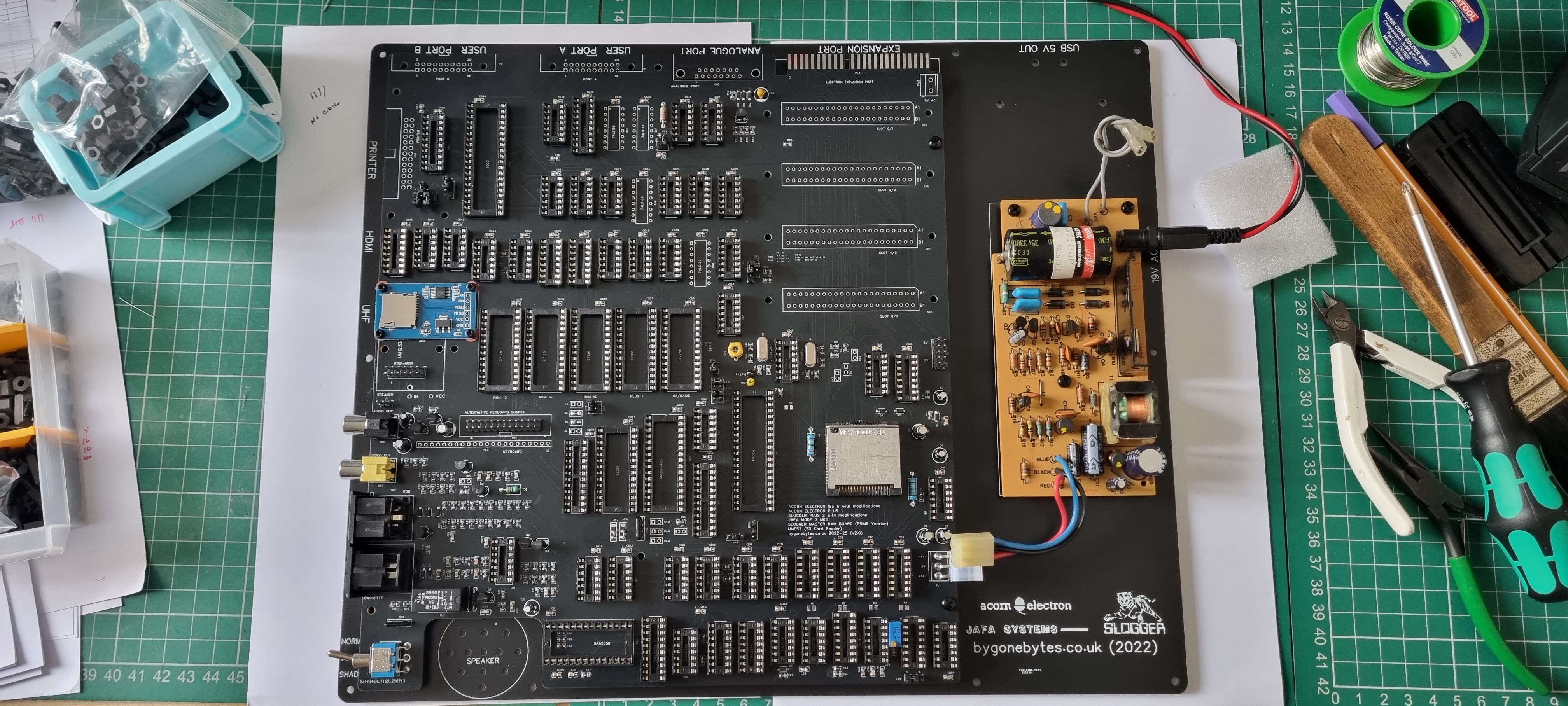
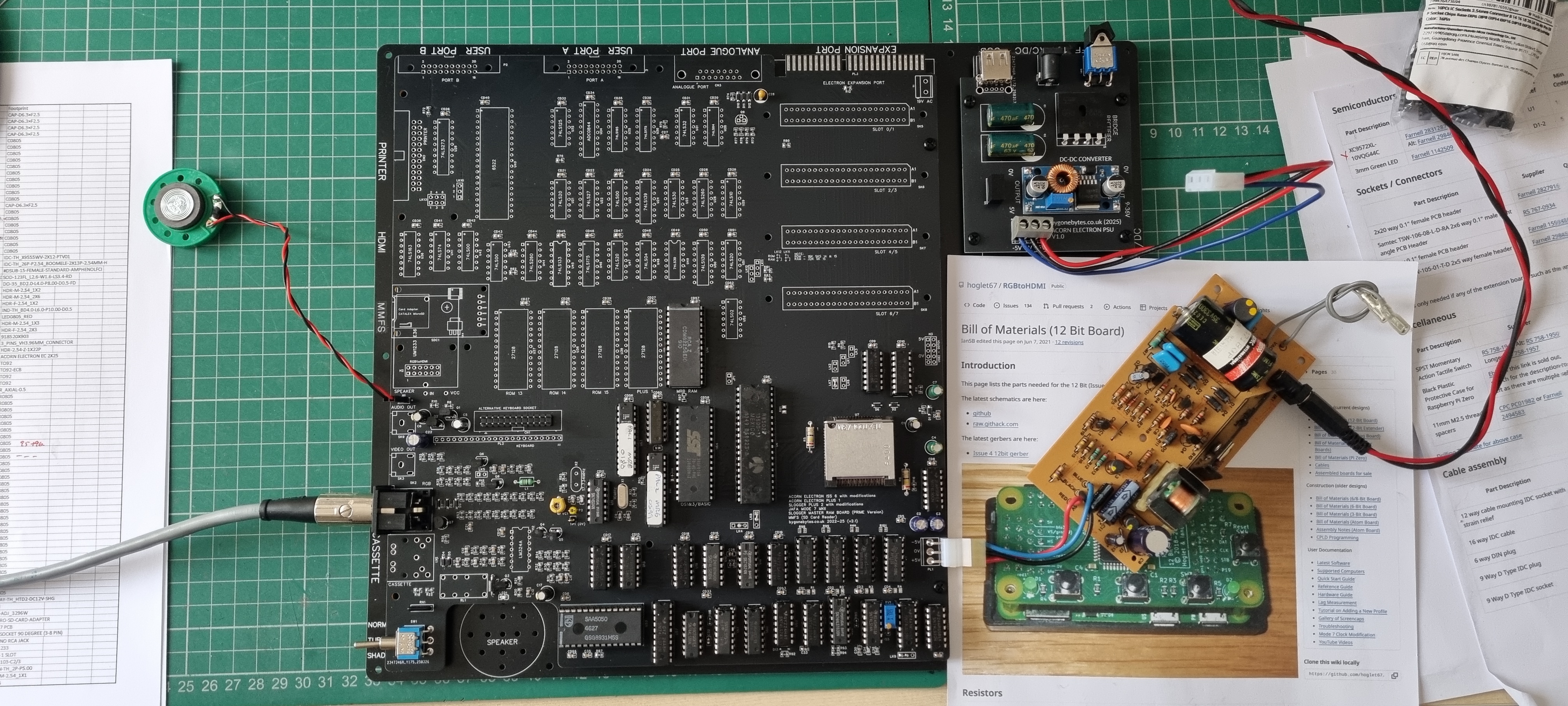
While all this is going on I'm watching the power used by the system. I'm using a bench supply set to 15V to power the Electrons own power supply so the power reading can be used to calculate how much current at 5V the Electron is consuming (allow a little or a lot leeaway for efficiency). This is going to be interesting when trying out different cartridges.
The basic Electron - approx. 932mA and the Electron with the Plus 1 & 2 - approx. 1.15A - calculated 5V current.
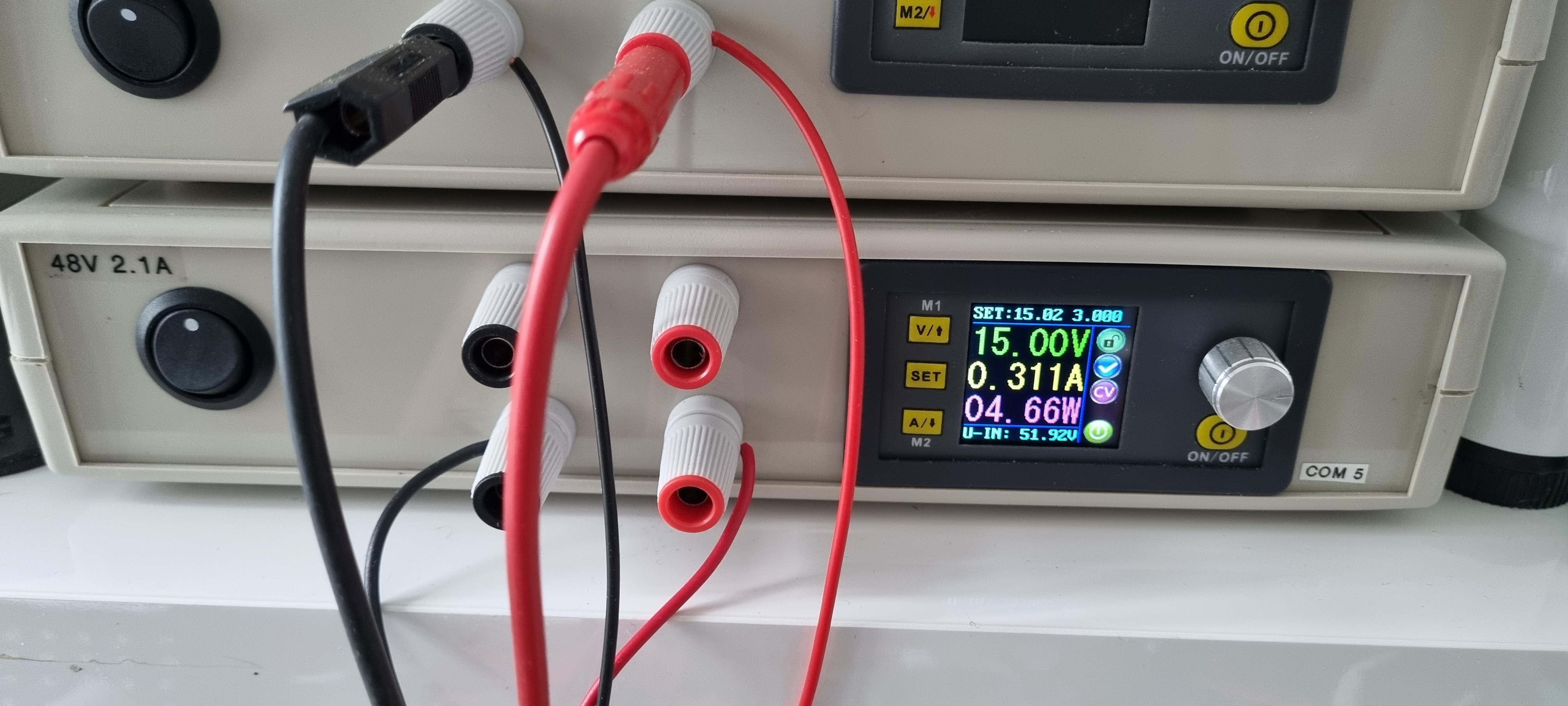
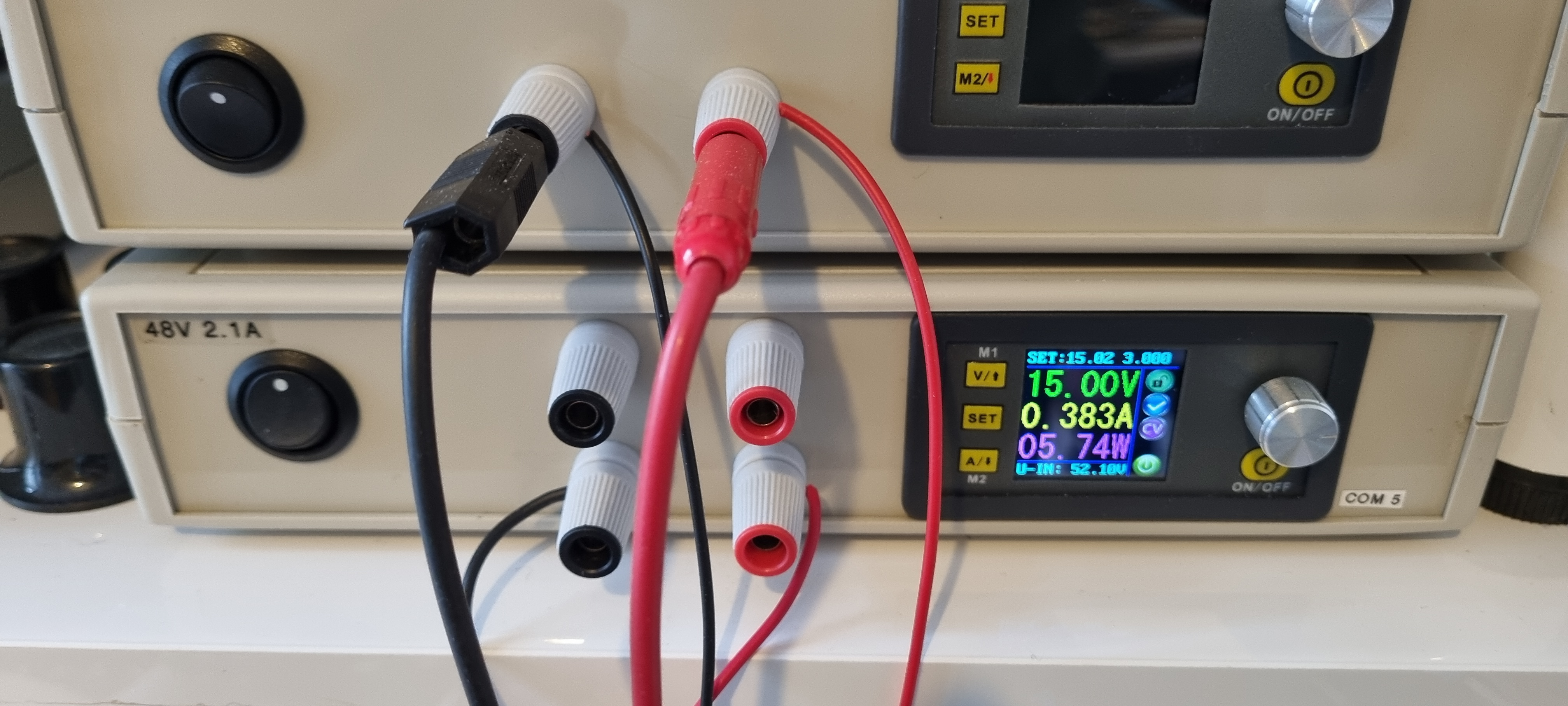
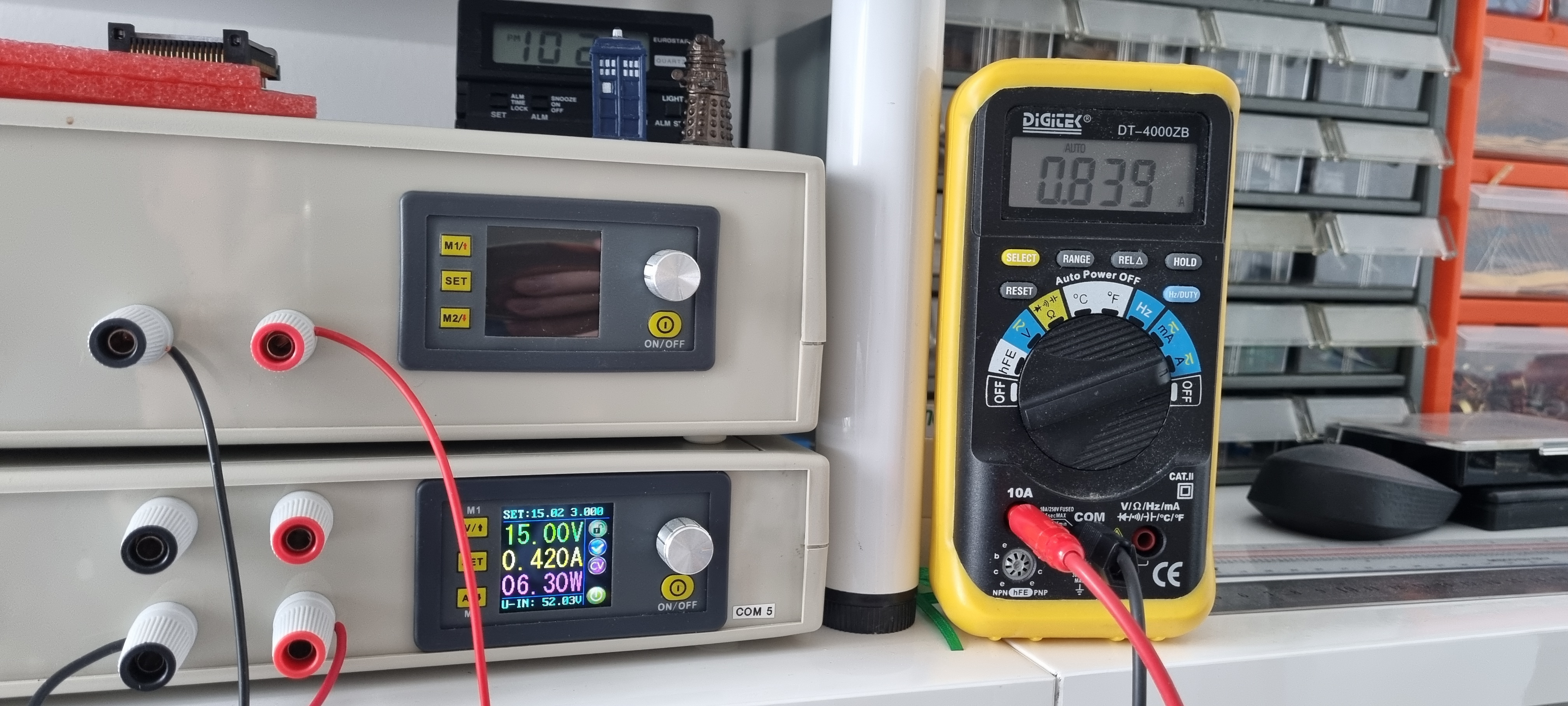
The Electron with the Plus 1 & 2 and the Pegasus Disk interface and ROM card - approx. 1.37A. The second photo shows a meter in line with the Electron 5V PSU connector displaying the actual current drawn by the board (839mA - 4.2W) and the PSU shows the Input current (420mA) & power (6.20W). This setup is very inefficient!
Now back to the build..
All the IC's are in and it's time to test the User and Analogue ports.
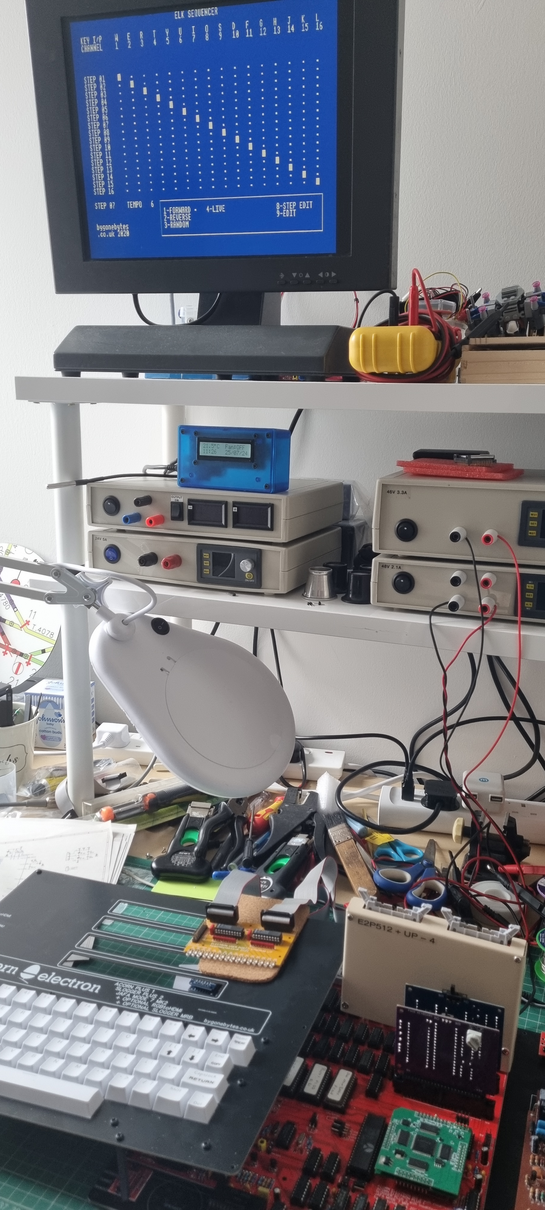
At the moment I am just going to check the User Port as outputs and one analogue input simply because I can do this with my sequencer program.
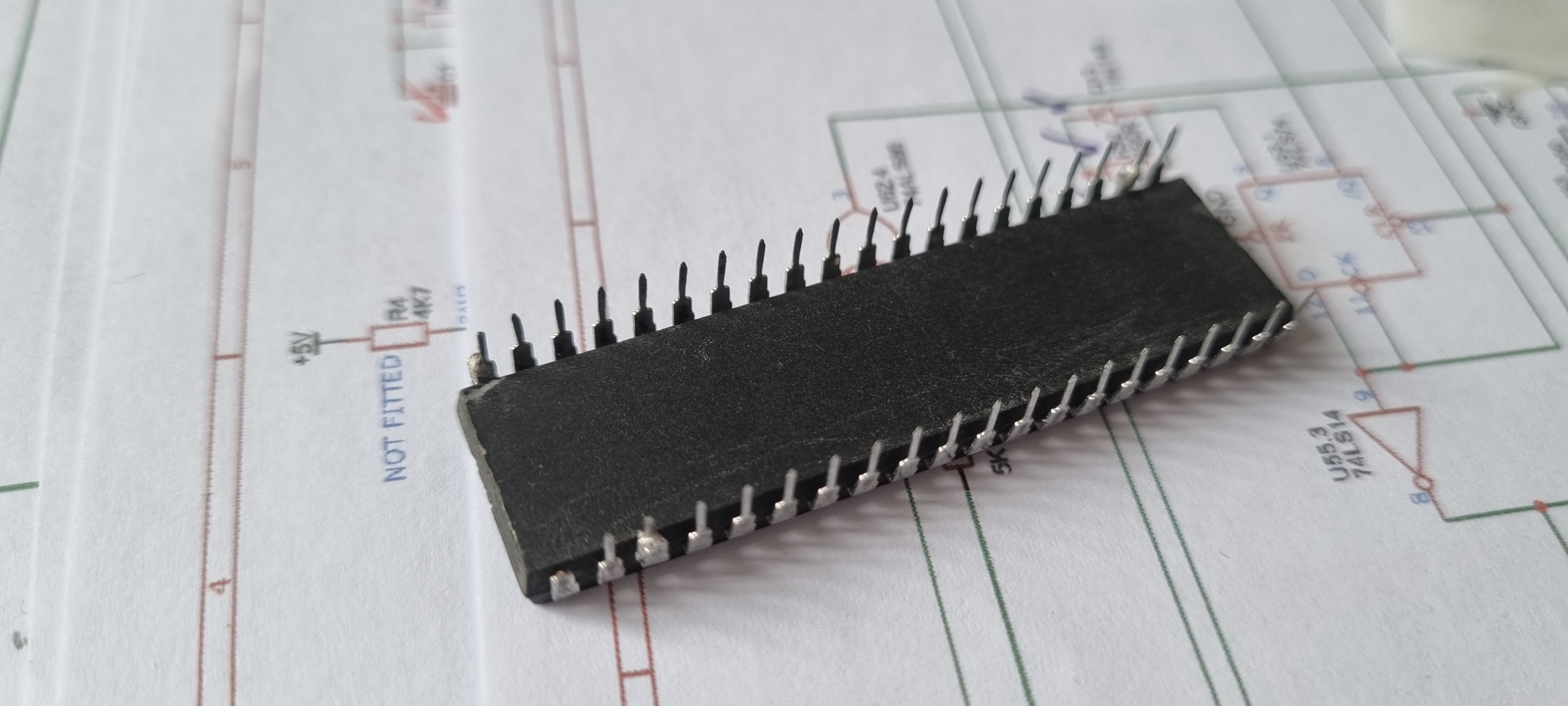
This didn't go well, only the first bit on each port worked so I took out the 6522 VIA and found that one of its legs was missing. I'm sure they were all there when I plugged it in! It can be seen this chip has been repaired in the past with some new legs soldered on. I replaced it with another one and I'll see if I can fix that one later. The analogue port worked fine.
Checking the Mode 7 worked by tweaking the pot until I got symmetrical characters then run the above 'Hello World' program with the MODE 7 colour control characters added.
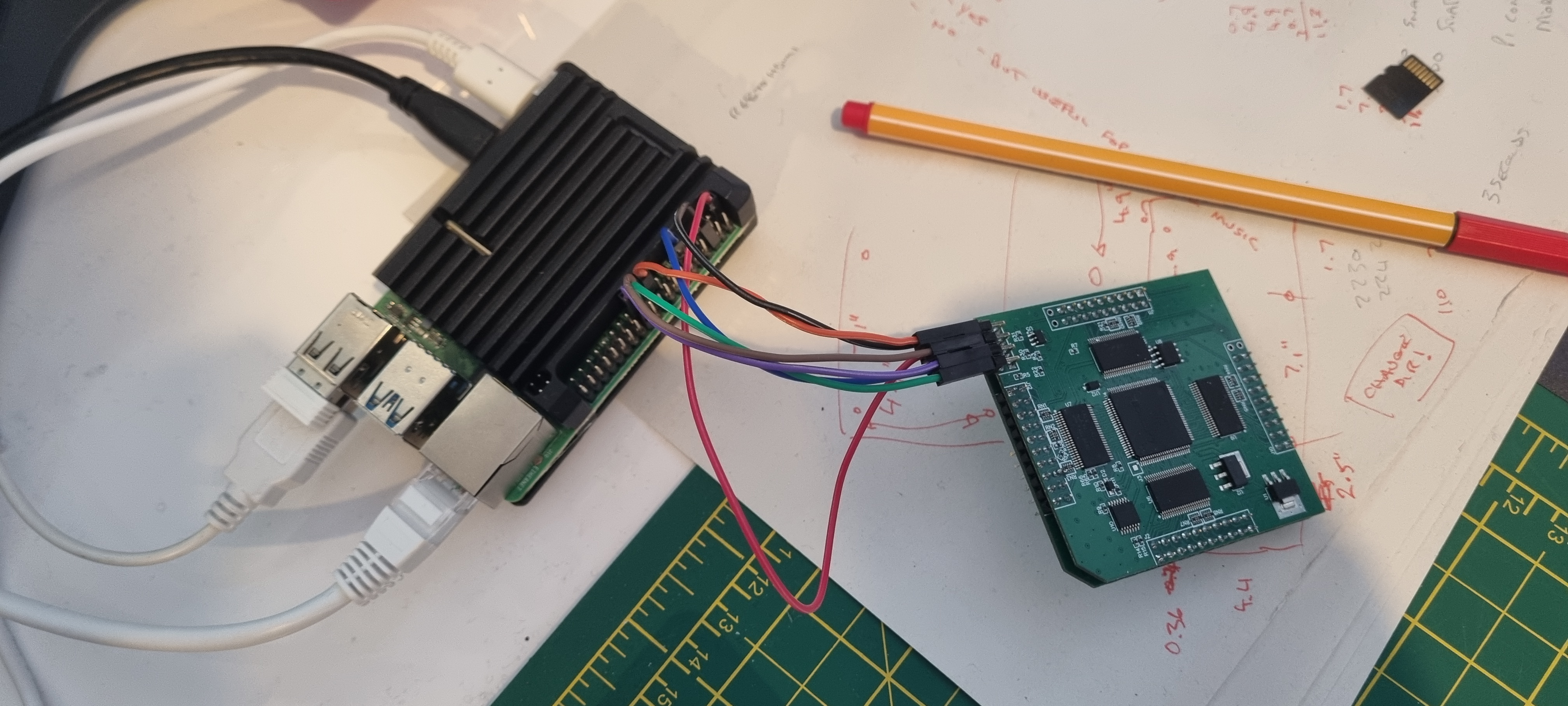
Next up was to update the software in the ULA as this one was shipped with a little issue, the CAP LOCK LED was inverted. I followed the instructions for the Raspberry PI on GITHUB but got stuck when I didn't realise that when issuing the program command I had to do it within the directory that had the new binary. Once I new that it only took a couple of seconds to re-program - my inexperience..
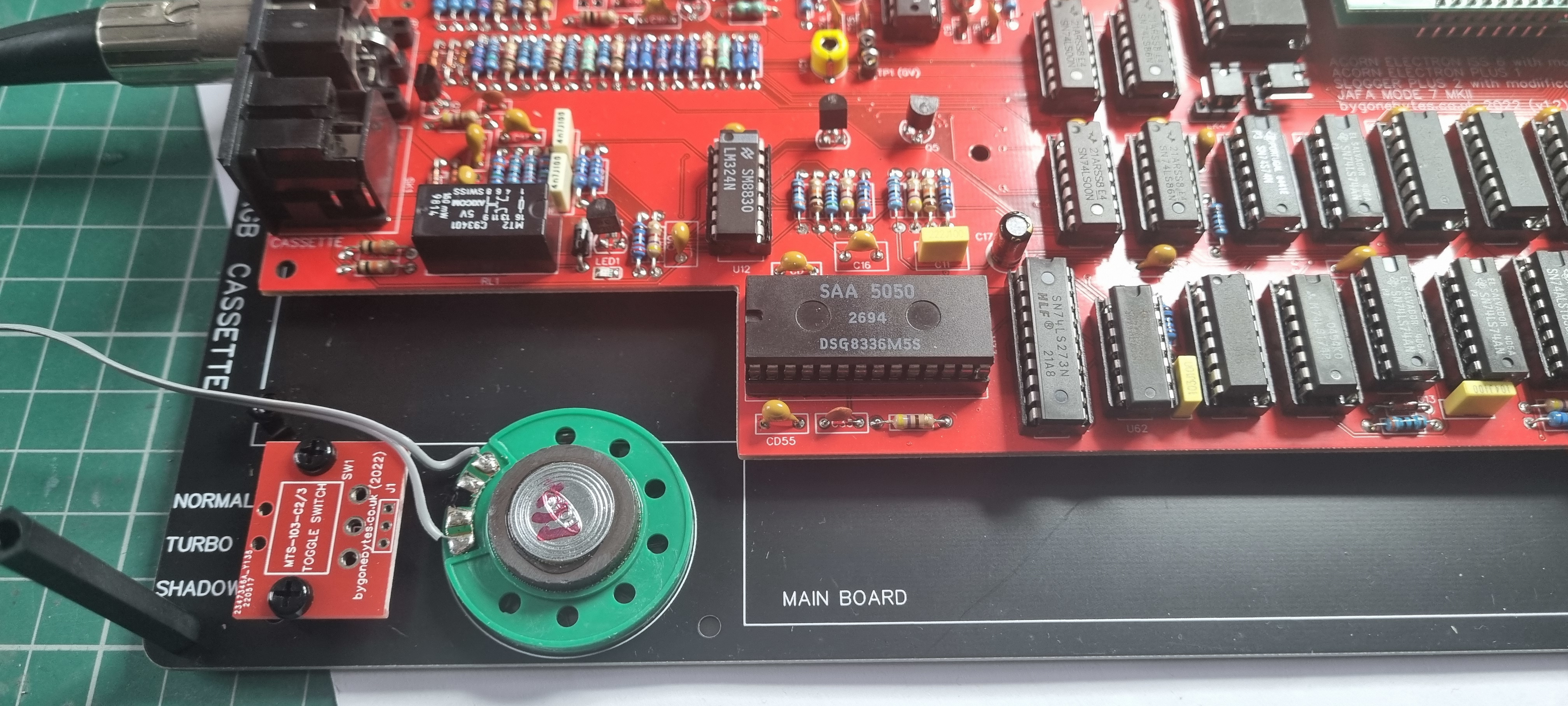
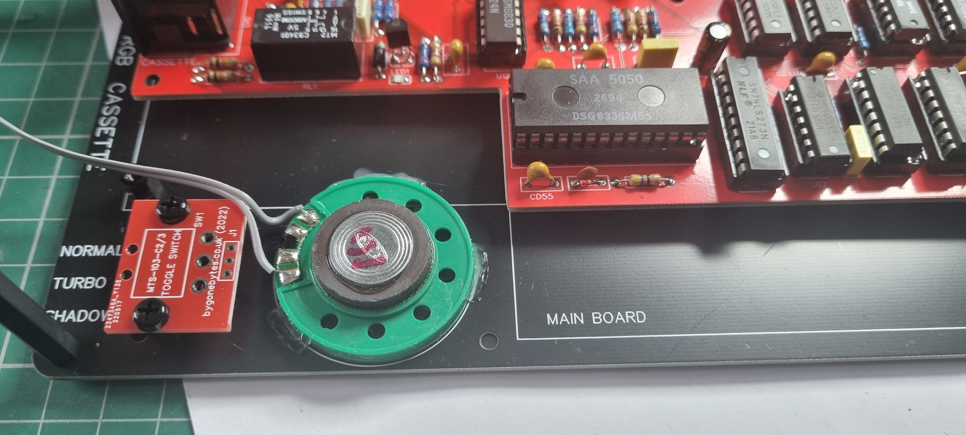
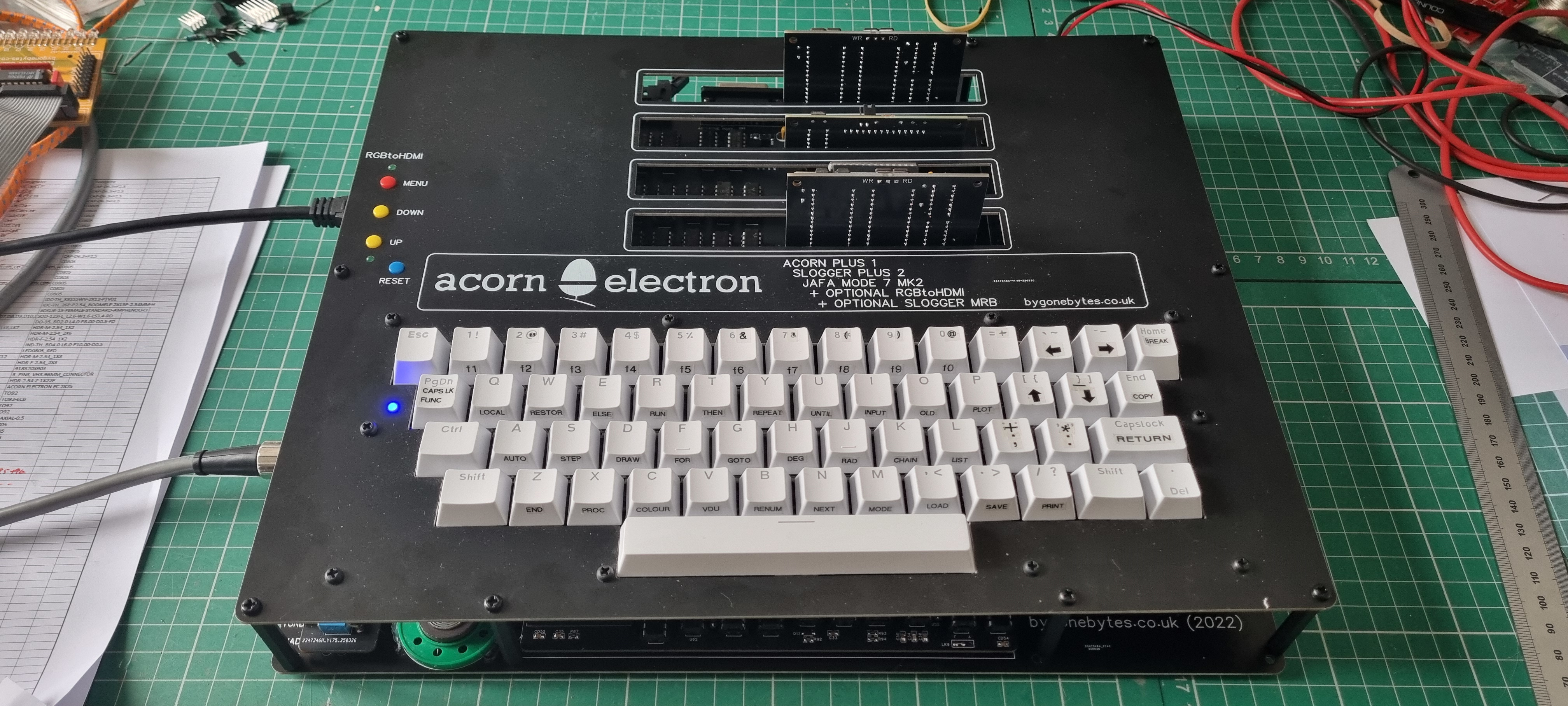
Now for the final assembly. Gluing on the speaker in its position with a little hot glue.
Fixing the pillars in place and fitting the lid.
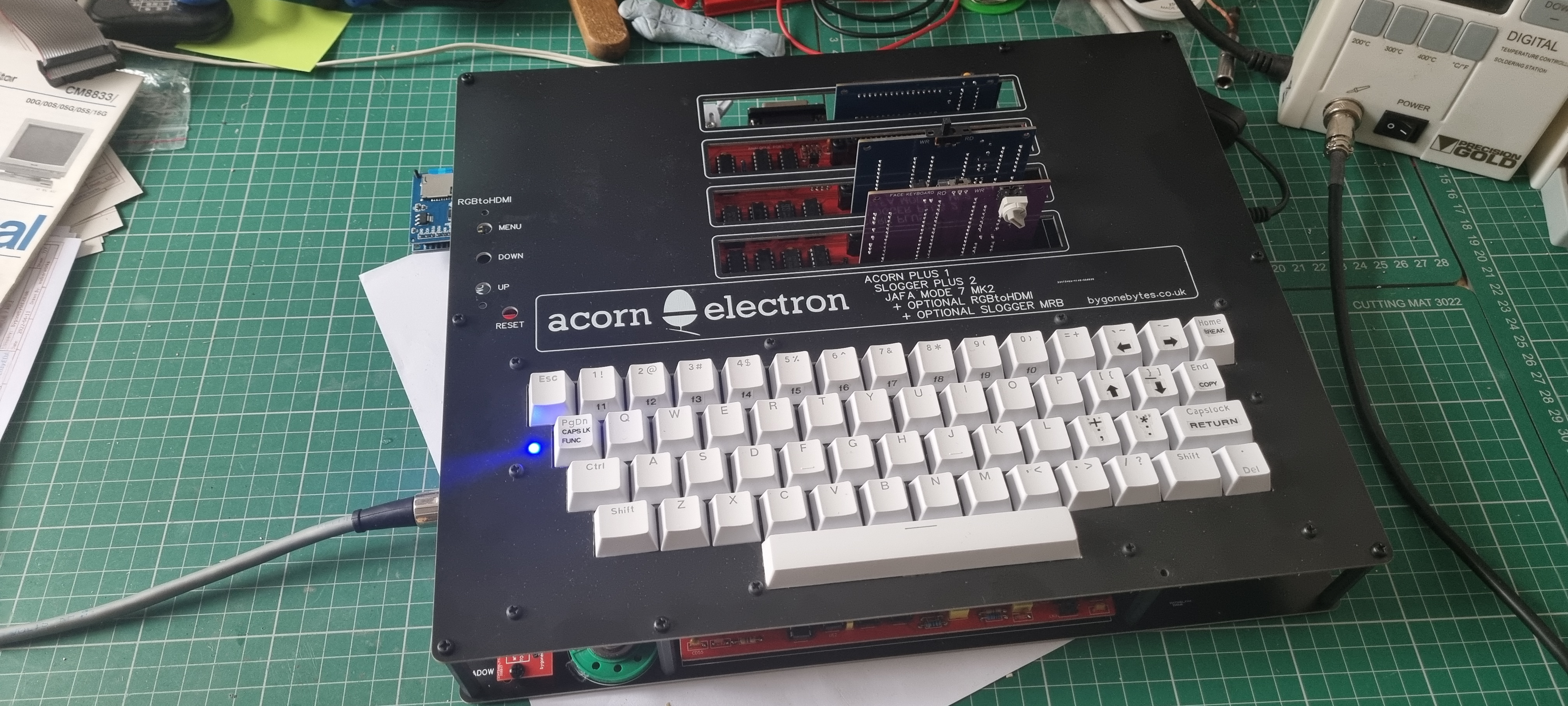
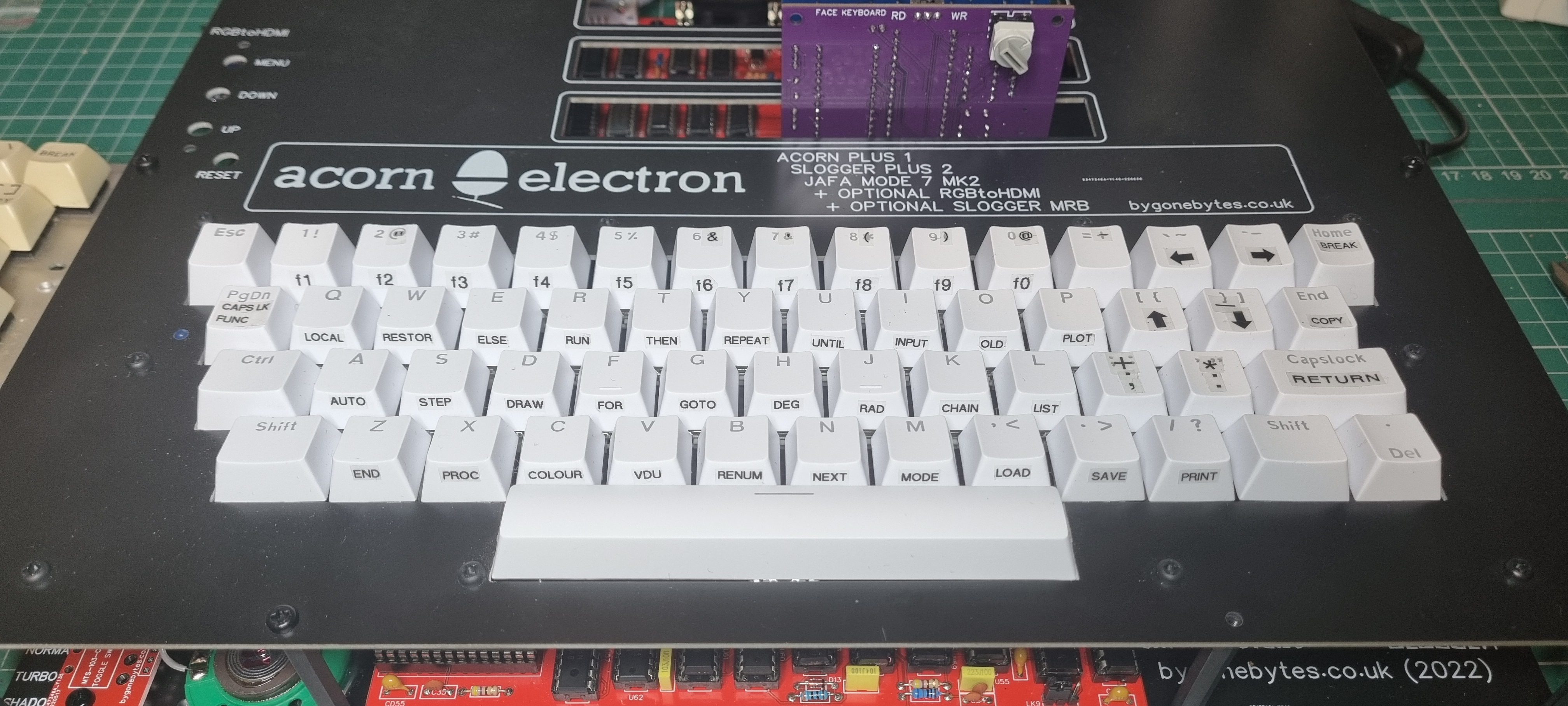
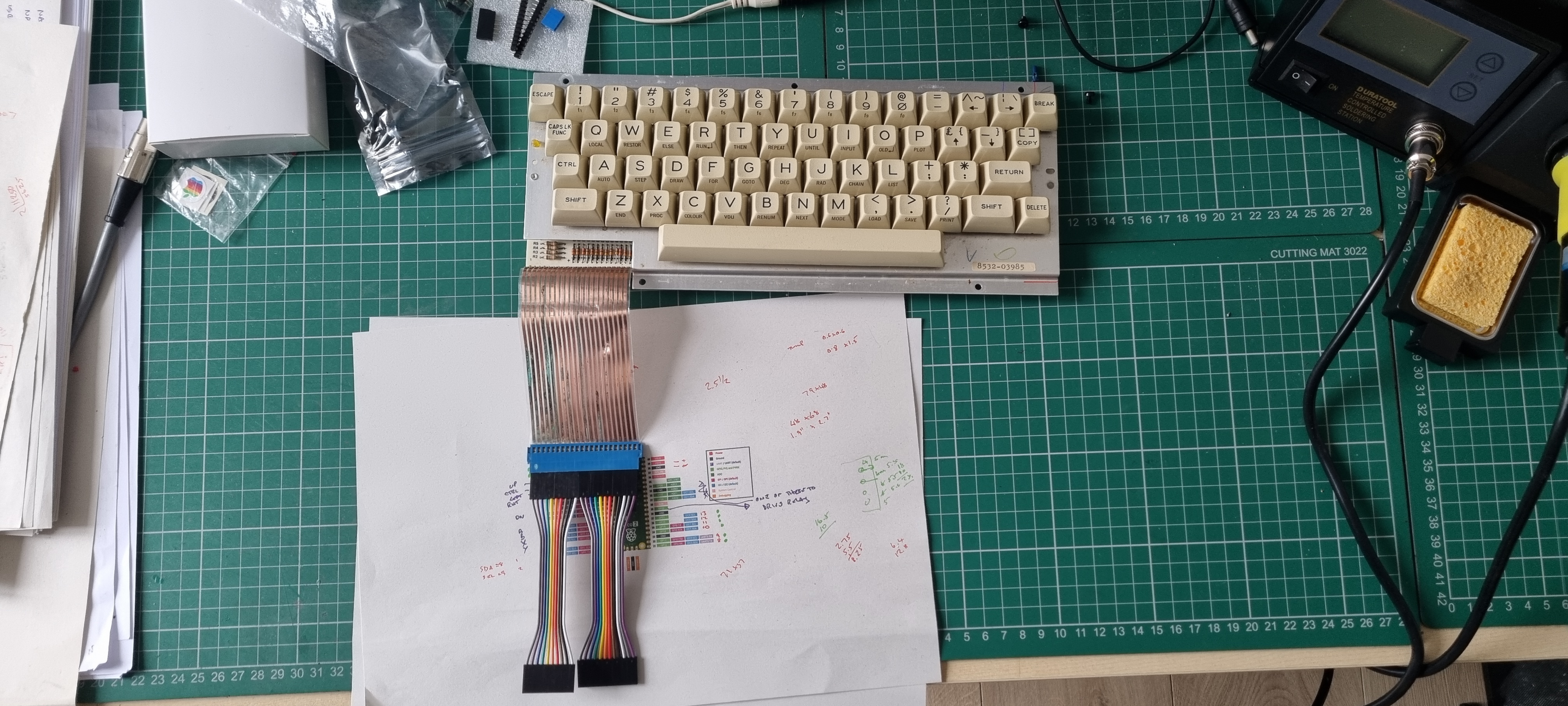
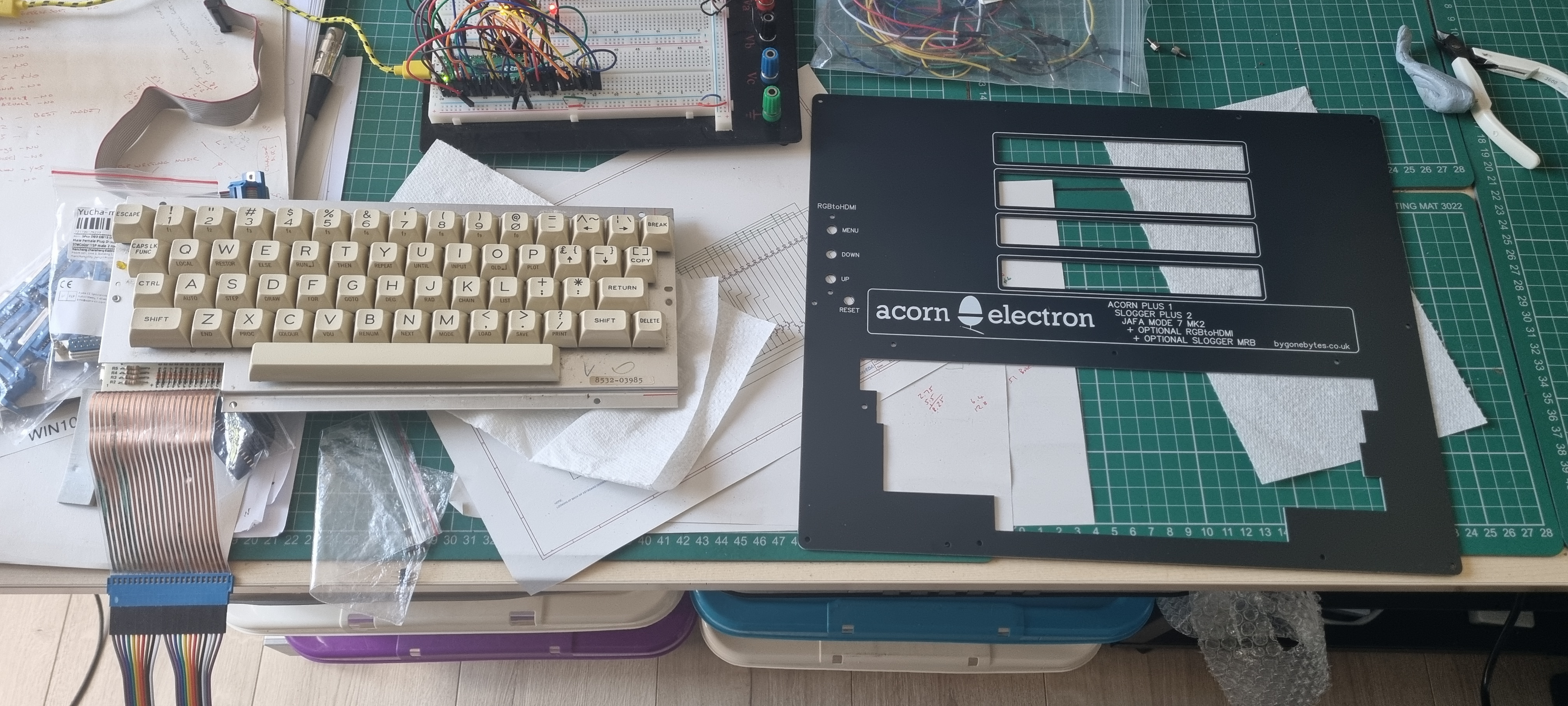
I thought I'd 'dymotape' some labels on the keyboard.
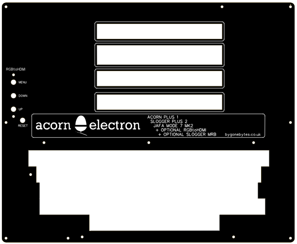
I recently got hold of a couple of faulty Electrons, I managed to repair one and the other will donate its keyboard to this build. To fit an original Electron keyboard I need to alter the cut-out on the faceplate, I could trim one of my existing faceplates but I would also like to widen one of the cartridge slots to accommodate my slightly deeper 2nd processor cartridge so a new faceplate is needed. I have completed the design and will order soon.
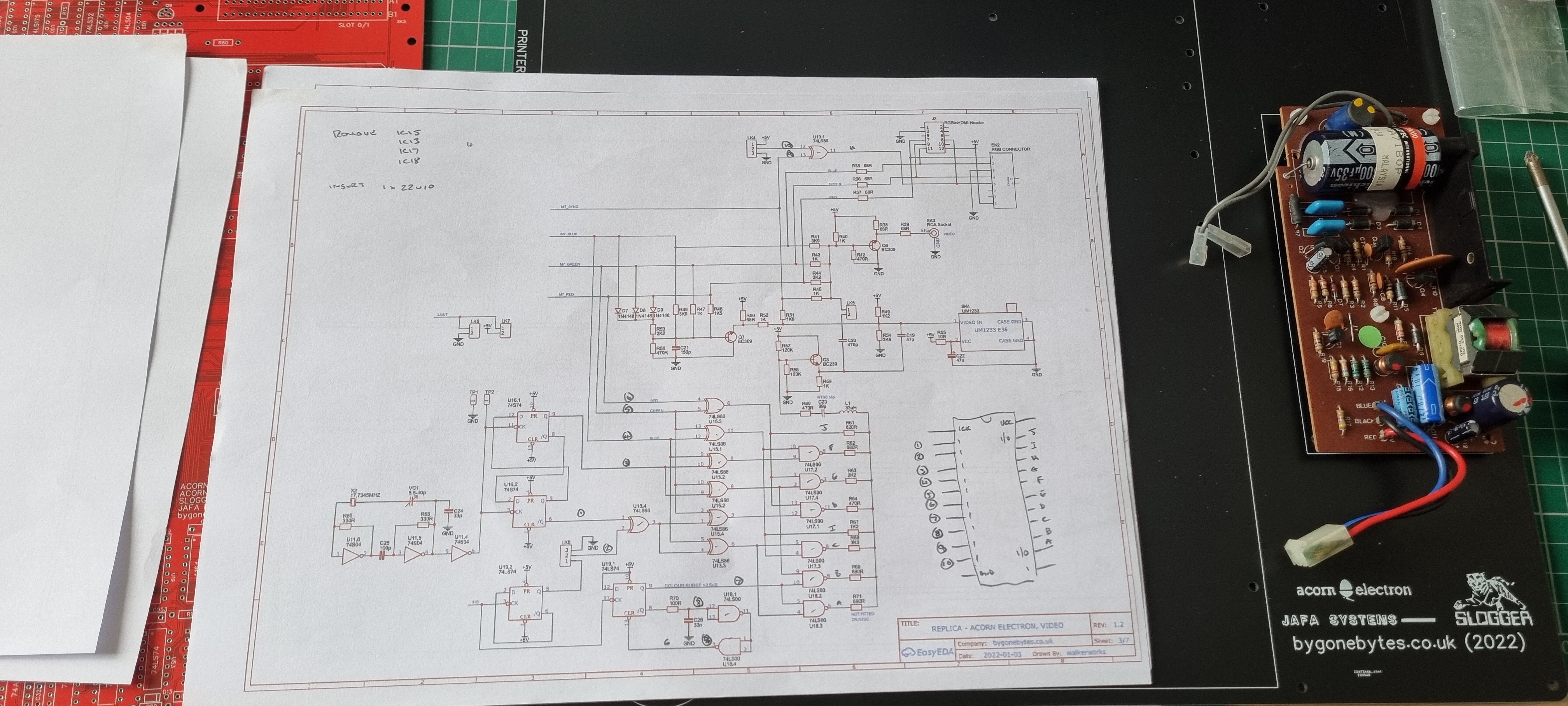
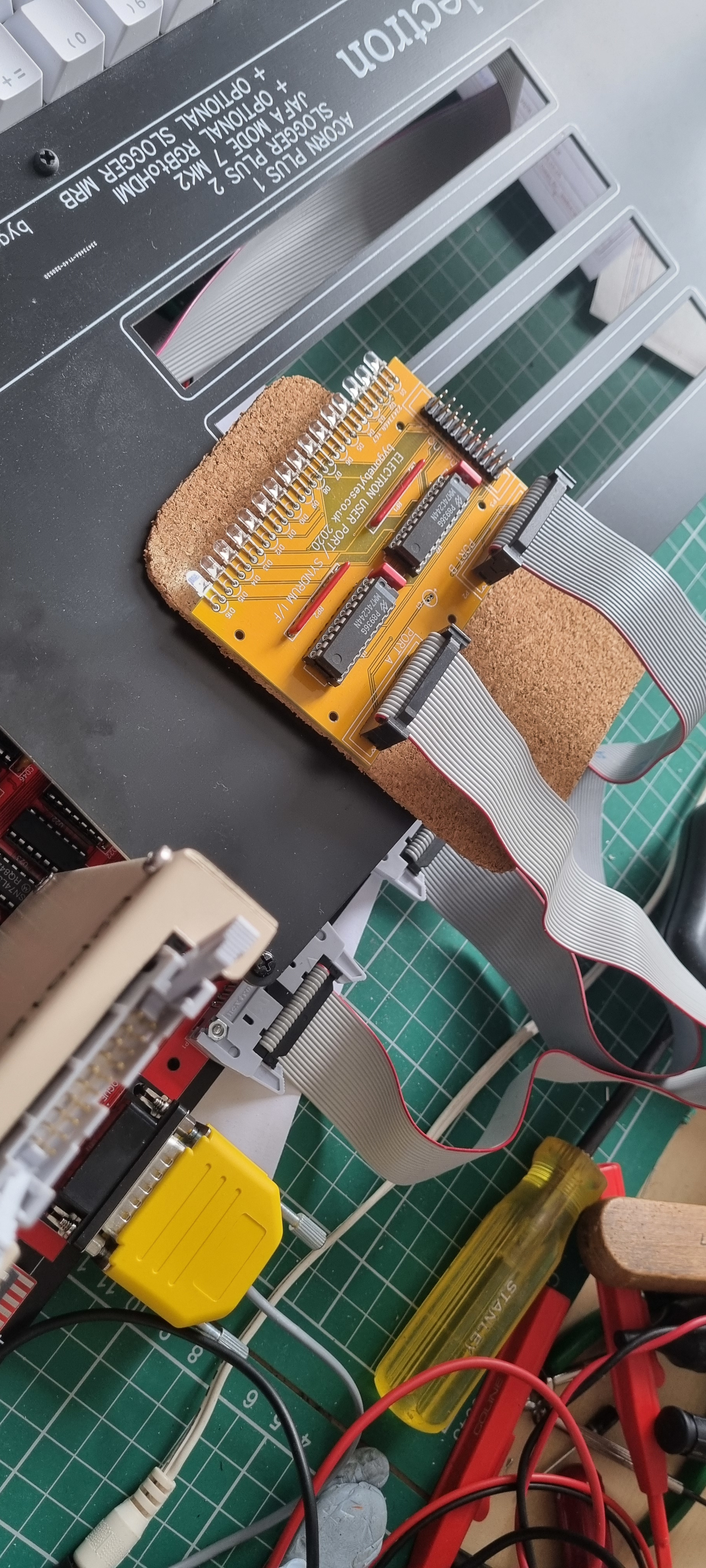
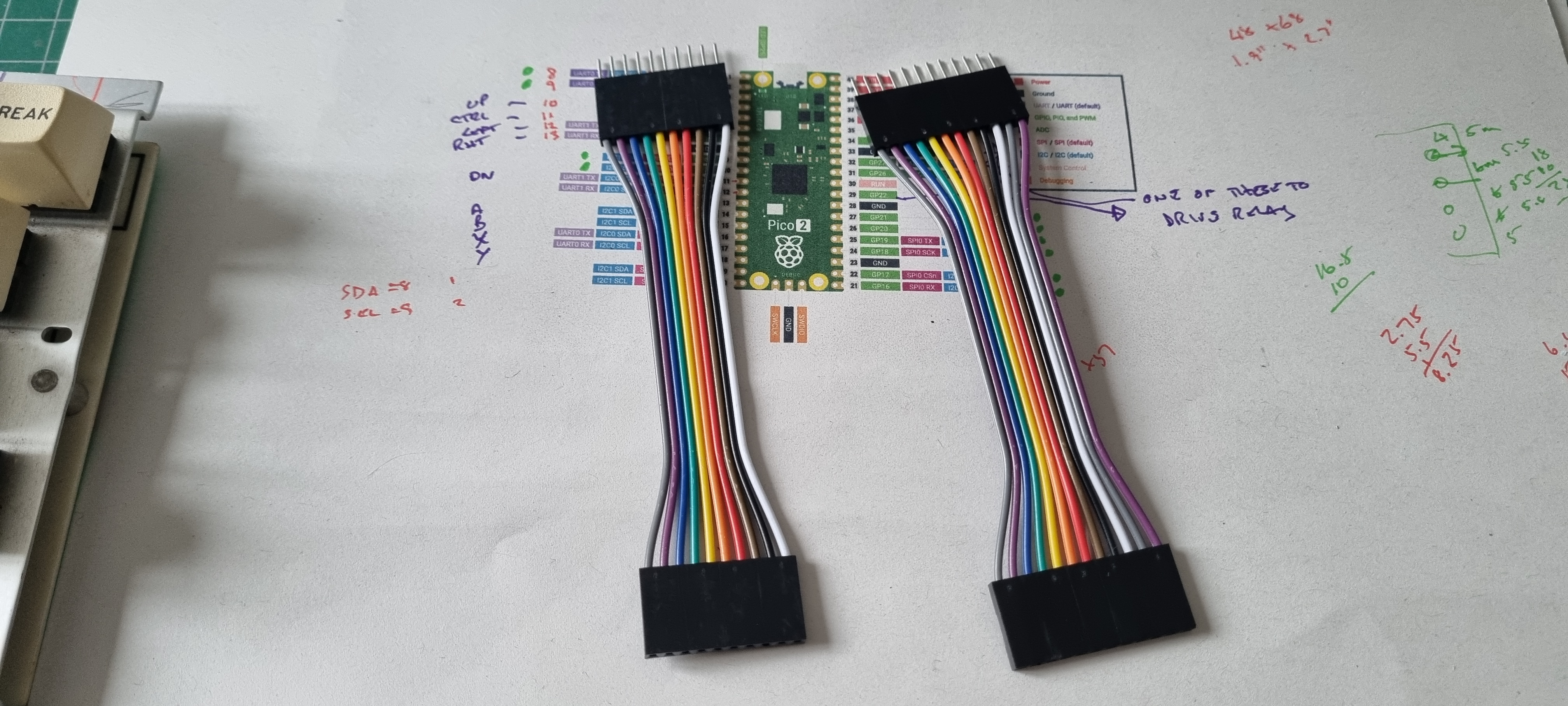
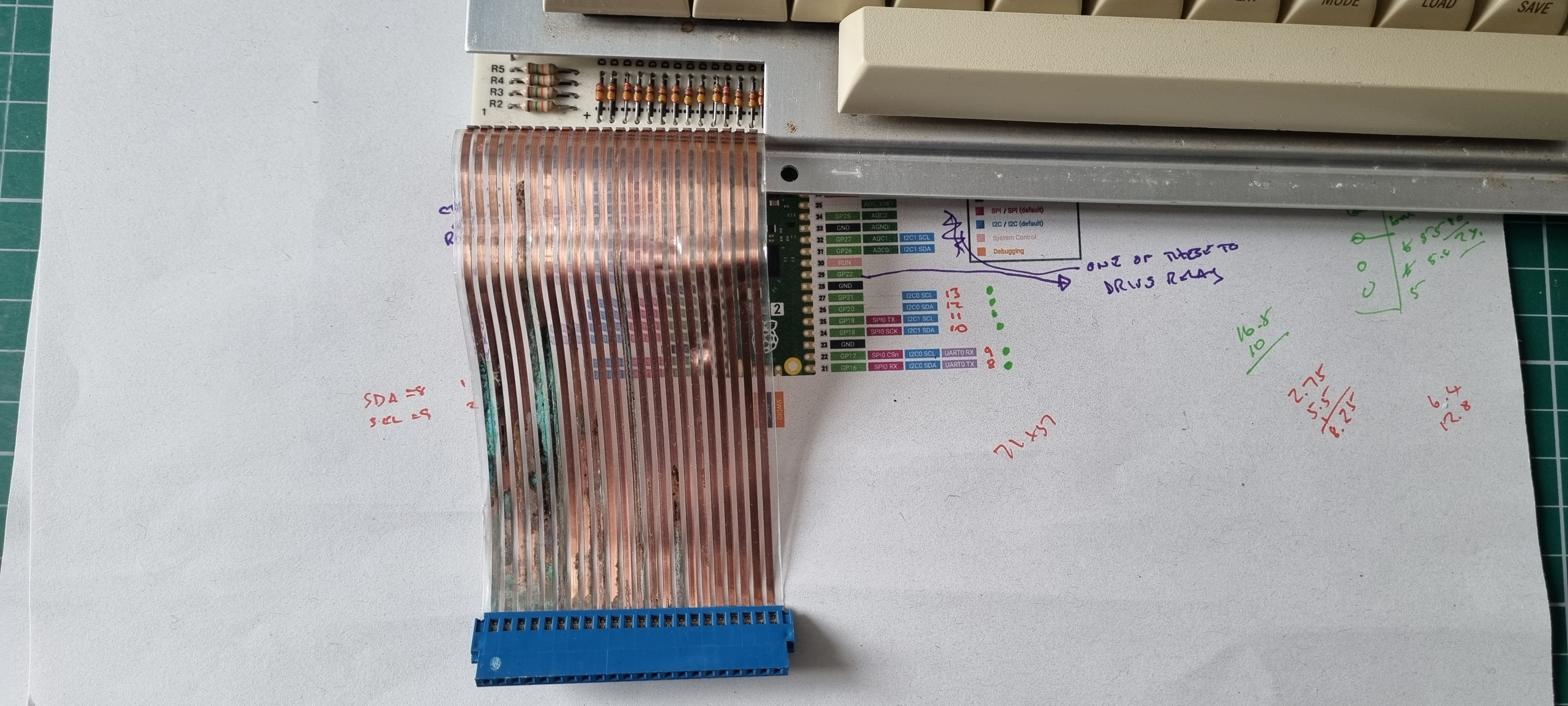
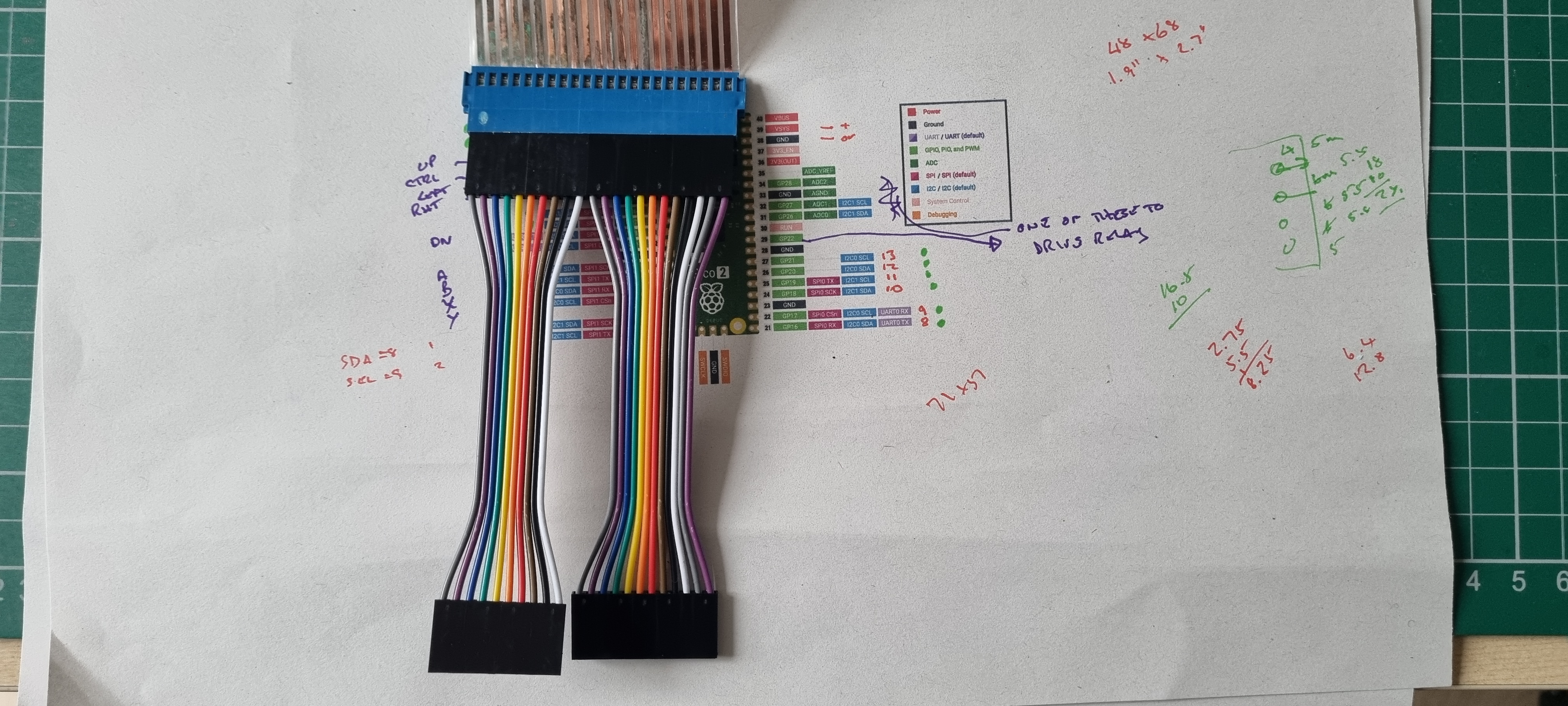
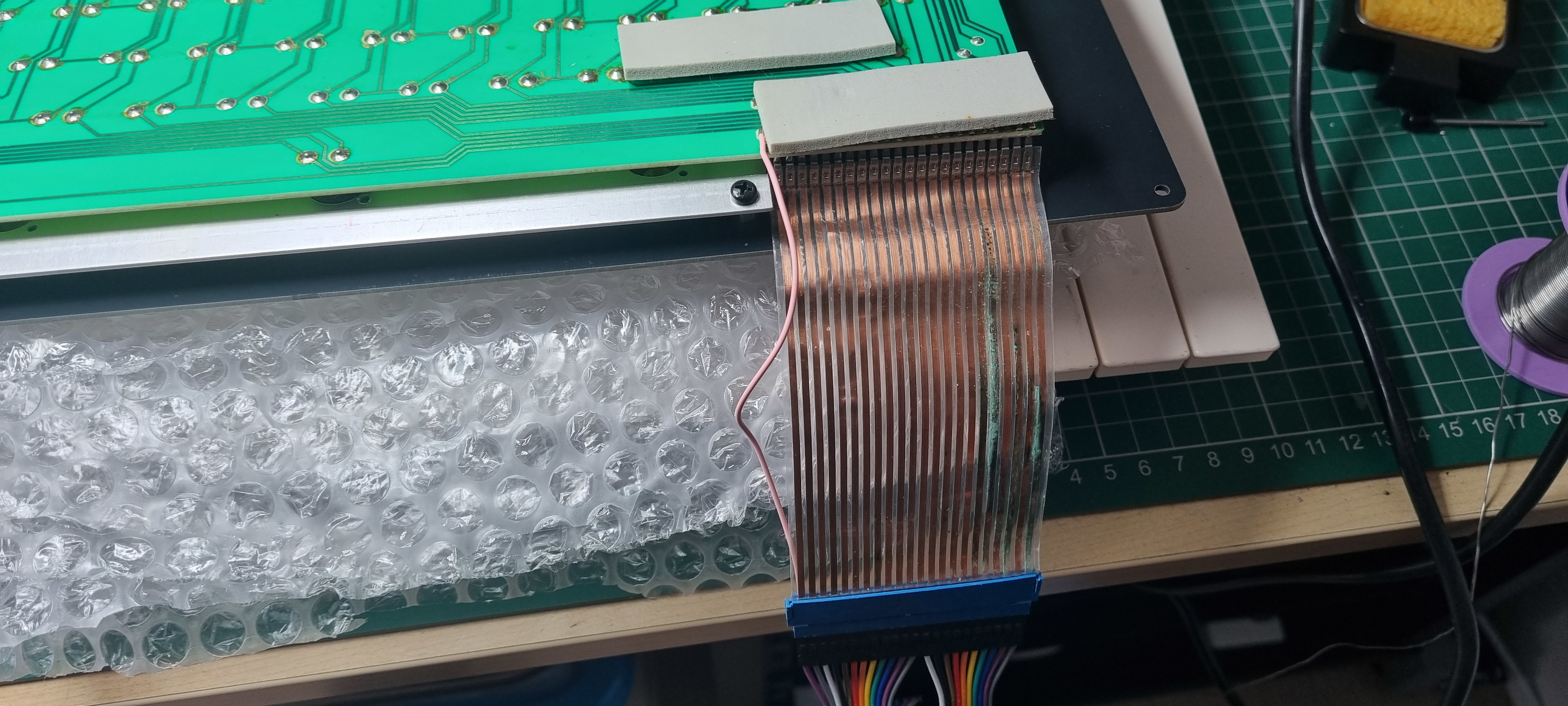
To fit the keyboard its ribbon cable needs to be replaced or extended, I opted to just to extend it by making up a short extension. I couldn't source a 22 pin single row header so I made it up from 10 and 12 pin headers. Still easy to attach and remove when needed.
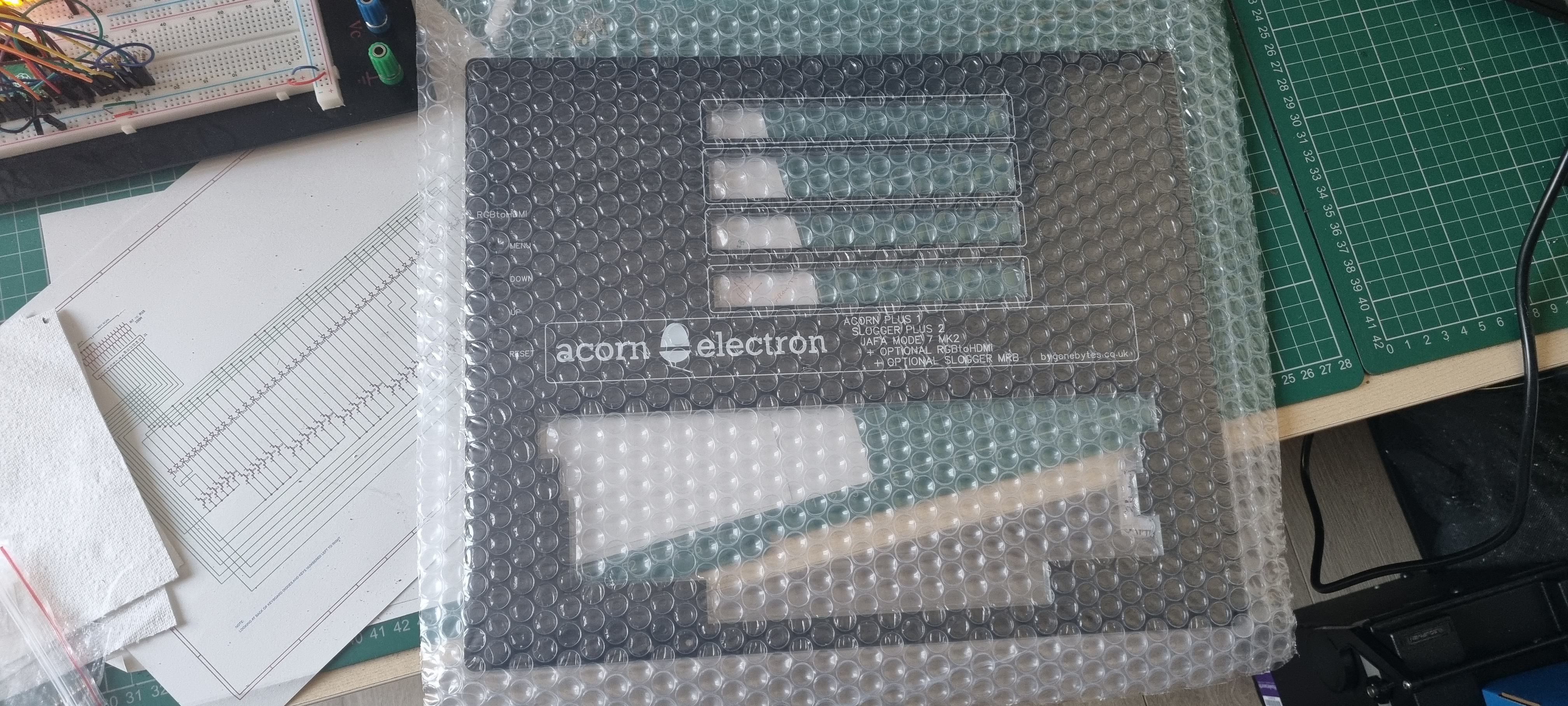
The new lid has arrived but I'll wait until the next ABUG scotland to see if it fits etc.
During ABUG scotland I fitted the keyboard - all the mounting holes were in the correct place but the space for the space bar is 2mm to the right. This is annoying but not a great problem, I have updated the artworks so any future panels are correct.
Two other problems came to light - prior to the meeting I replaced the CAPS LOCK LED but managed to fit it the wrong way round and during the meeting one core of the keyboard ribbon cable failed. Both of these problems had to wait till I got home and are now fixed.
I also took the opportunity to add an HDMI adaptor.
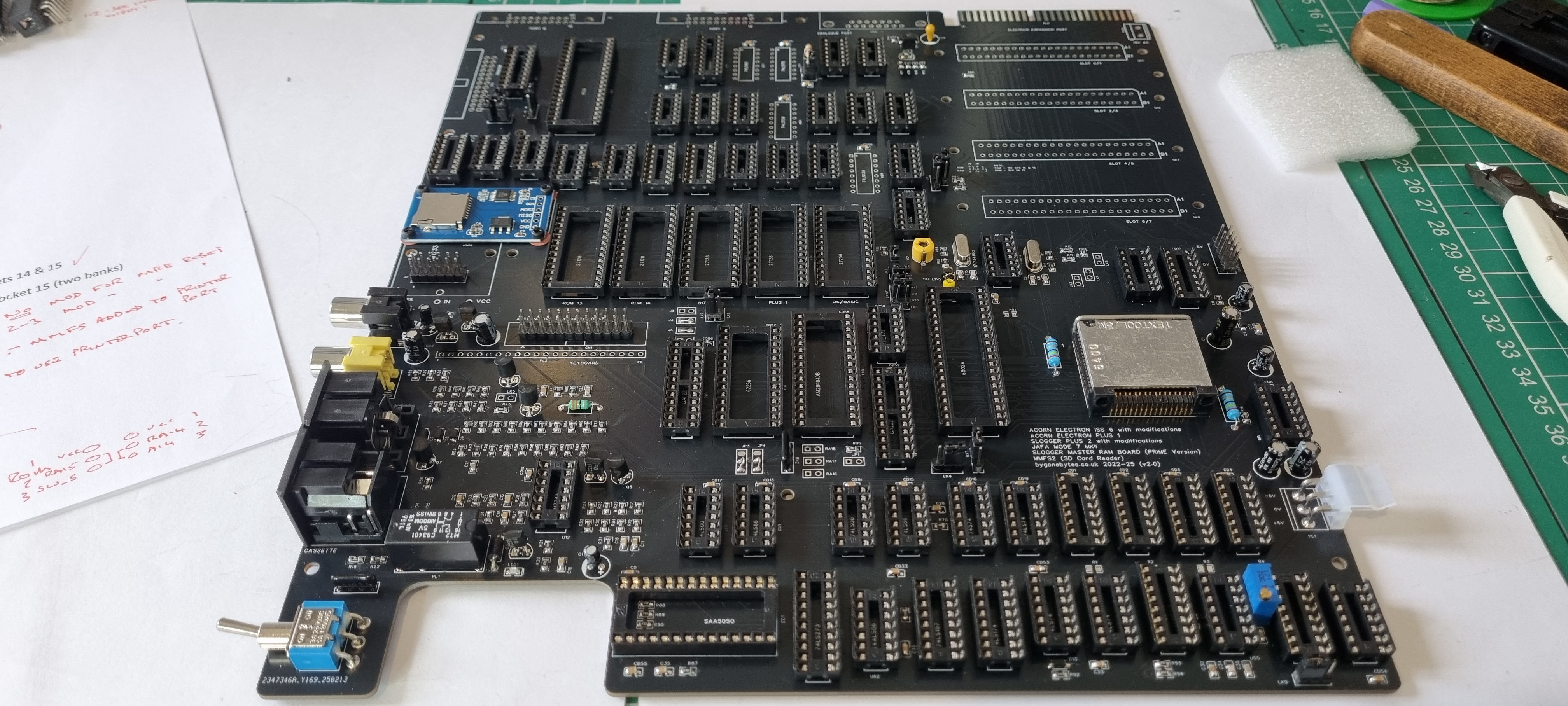
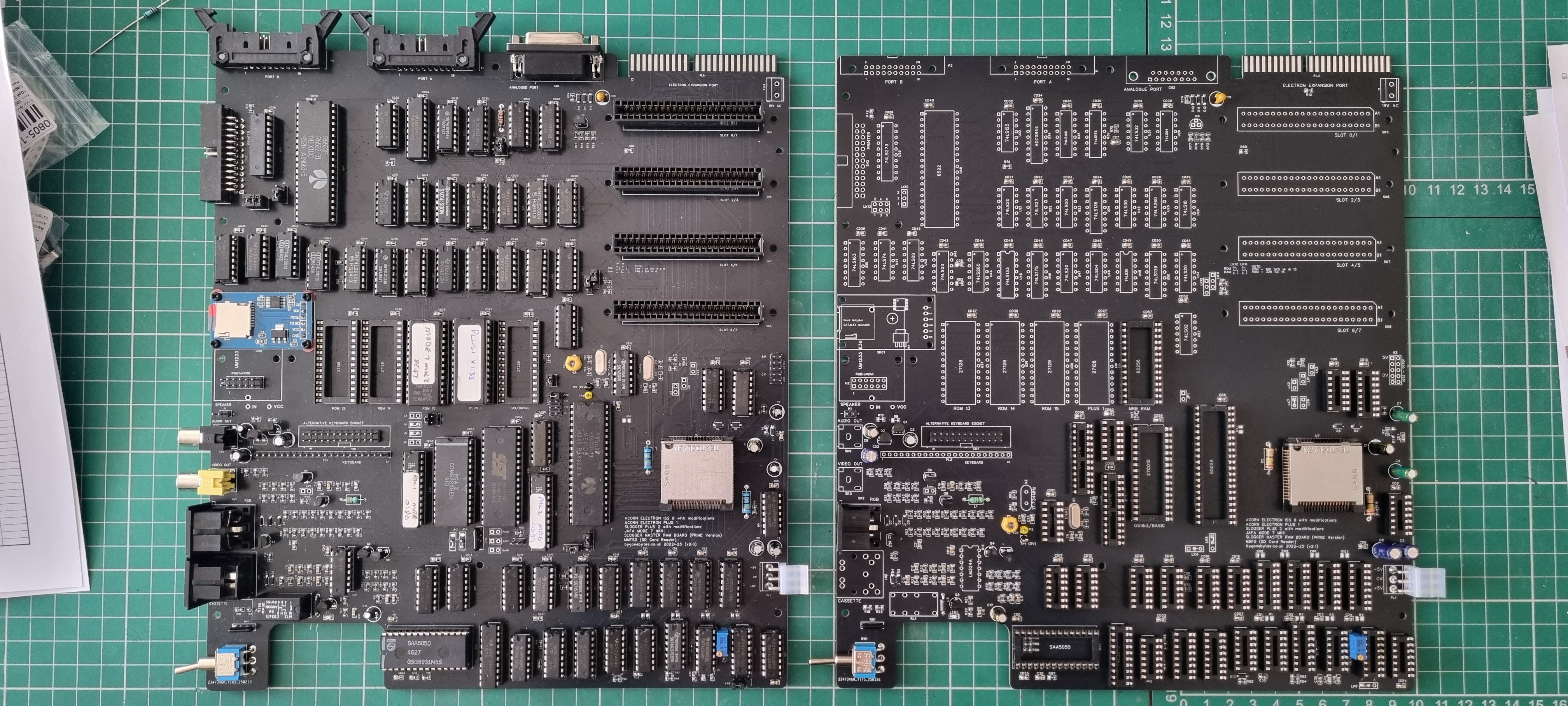
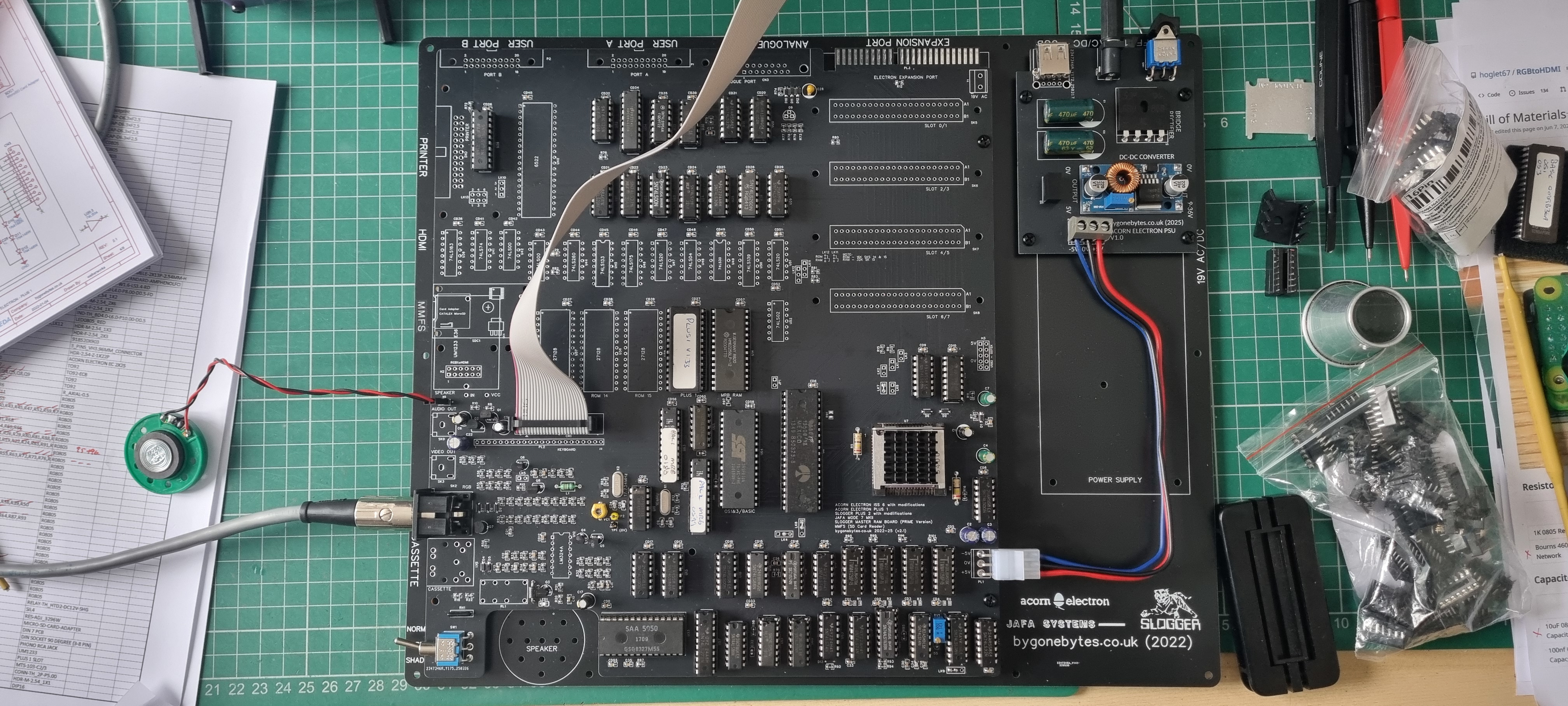
Finally got round to designing the layout for v2, it includes the MRB and MMFS2 but doesn't include the joystick interface or USB power socket. I haven't removed anything and still managed to squeeze on the Micro SD card socket but there wasn't enough room for the USB socket so the original header remains.
The PCB is now 4 layer as I found that there was a bit of a voltage drop across the earlier boards. At the power connector the voltage is 5.05V and by the time it gets to the printer port it roughly 4.85V, not enough to cause issues but I thought it would benefit from power planes on the centre layers (# the power is nice and consistent across the whole PCB, thumbs up for the power planes). I also changed most of the resistors and capacitors to surface mount to save space to make room for the MRB components.
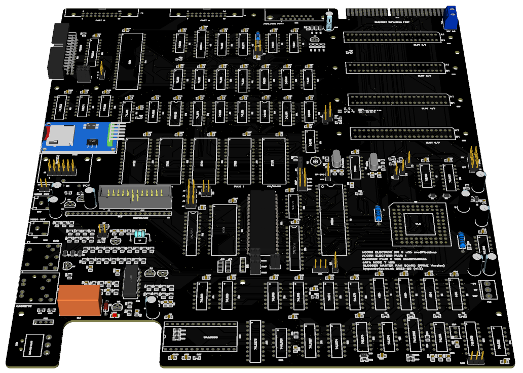
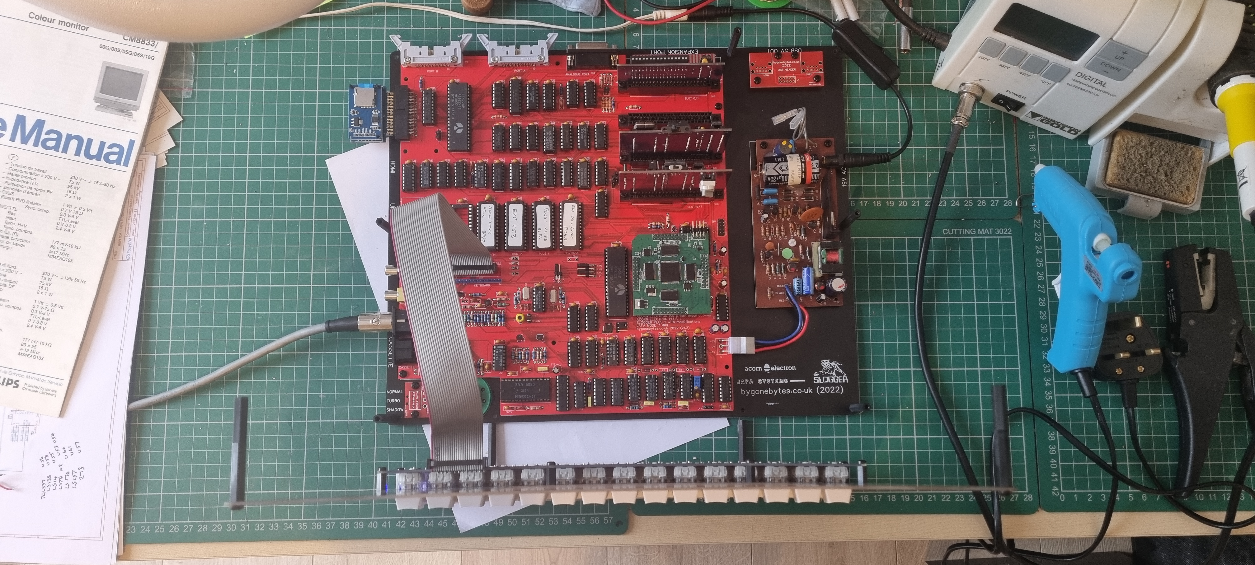
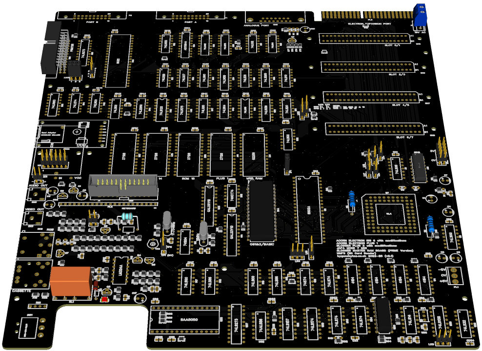
This is the new board. To free up space on the board to fit the MRB components I have moved the two oscillator circuits from the centre left to just below the the card slots. I have also changed most of the through hole capacators and resistors to surface mount which meant I could shrink the space the components at the bottom left uses. That gave enough space for the MRB, I also changed the shape of the board a little to fit the MRB switch directly on it. I found space for the SD Card module under the RGBtoHDMI board and added links to connect/disconnect it from the printer port.
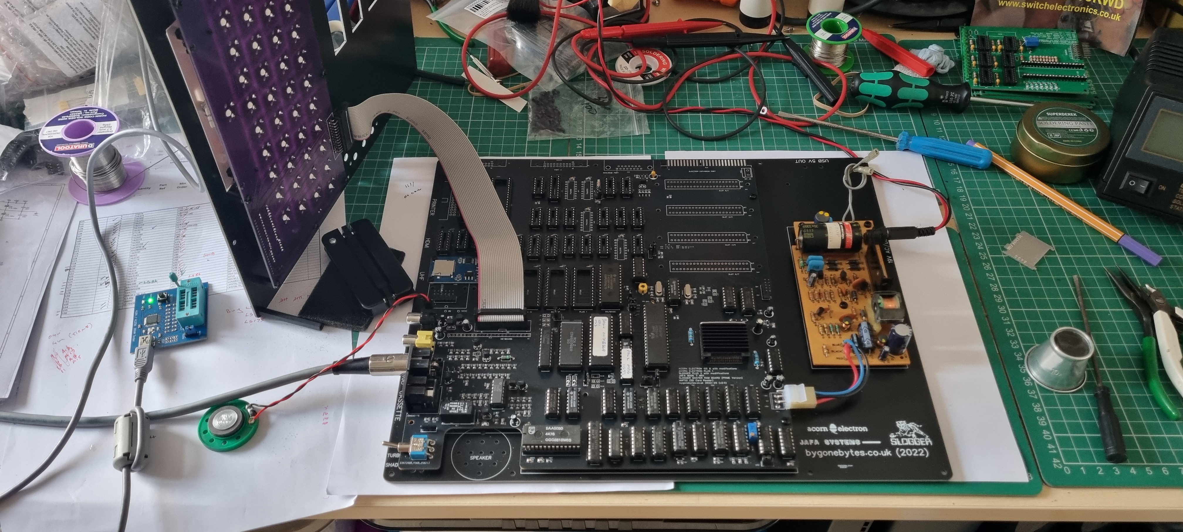
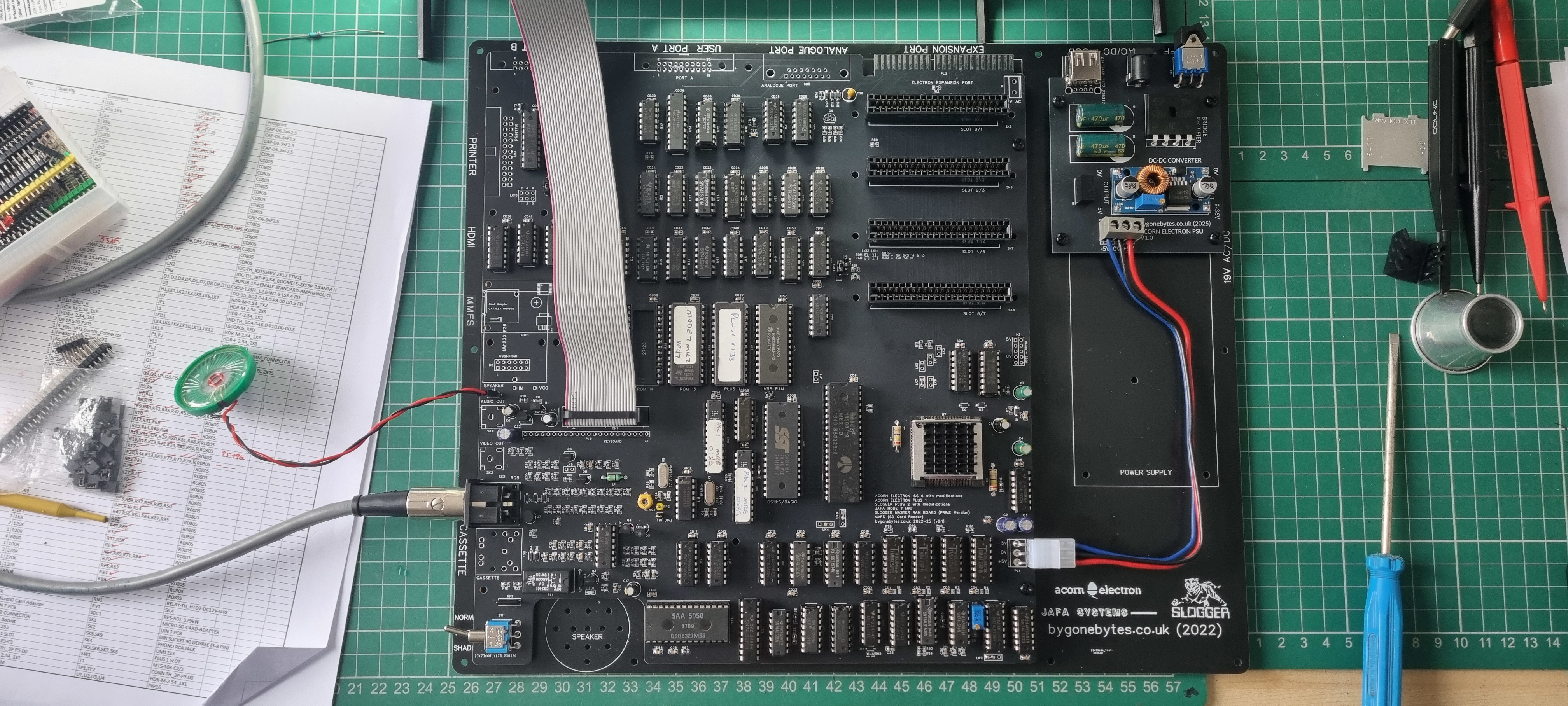
Lets get on and start the assembly.
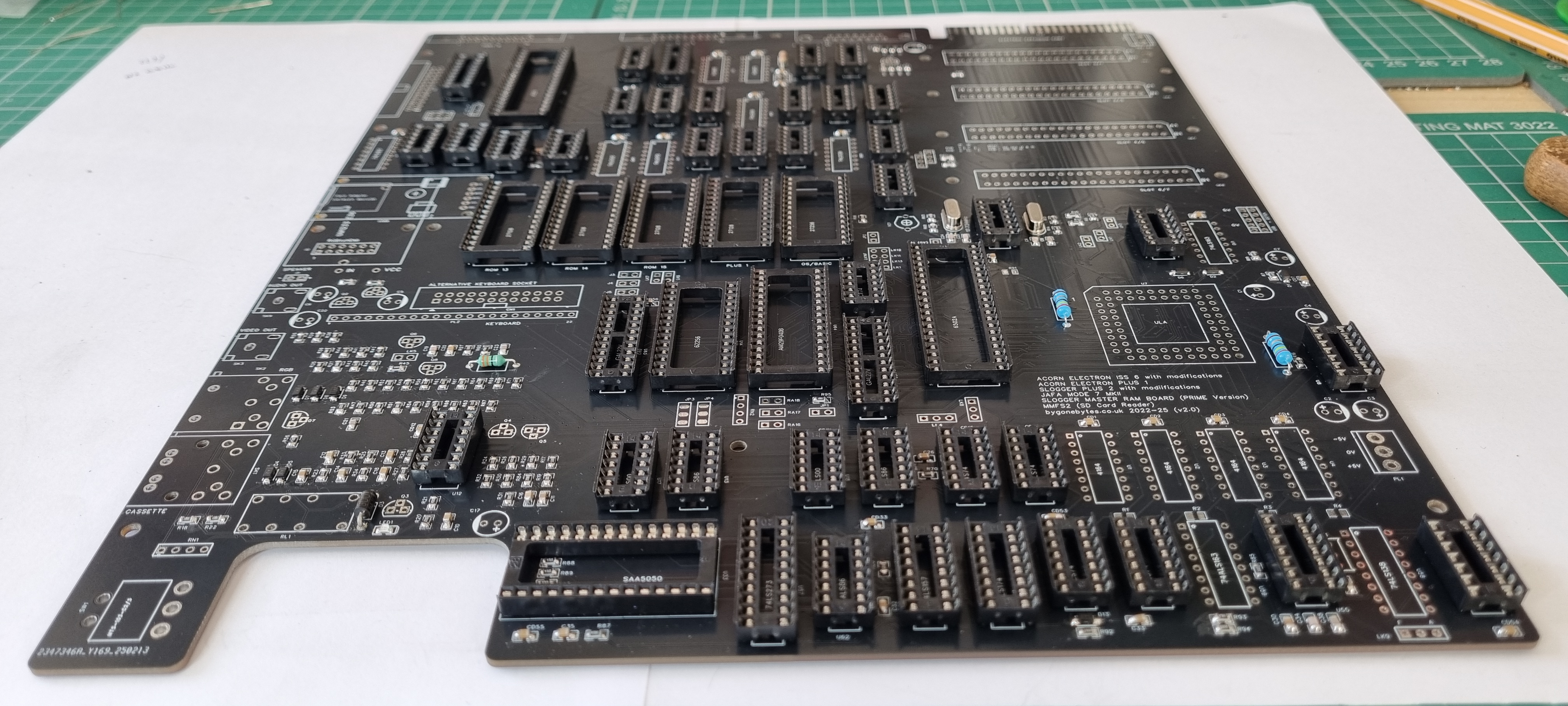
I did my usual and fitted all the passive components and sockets first.
Getting the test jig ready..
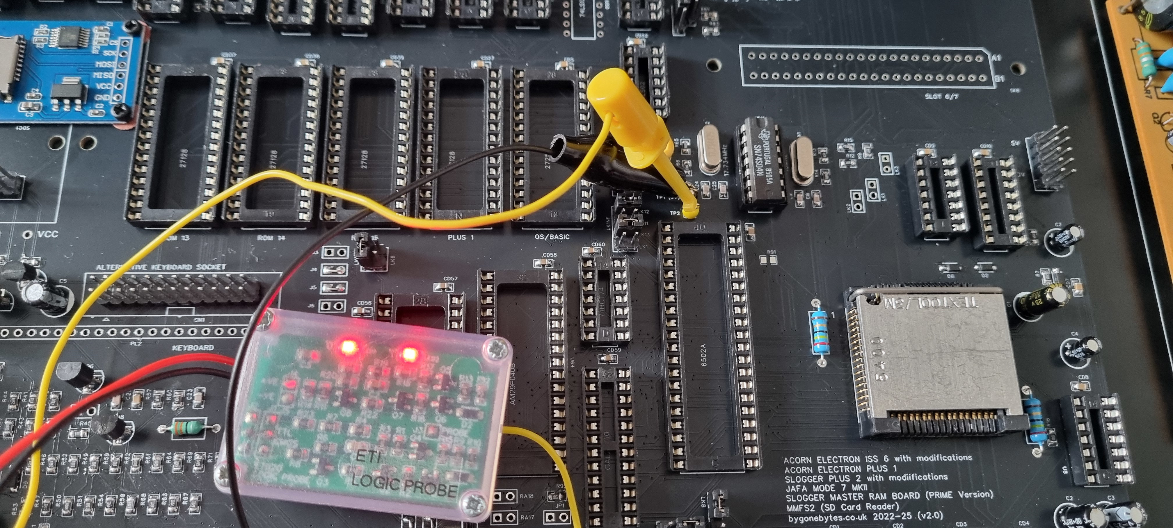
Checking the two oscillators are working using my logic prob. I don't have a scope at the moment..
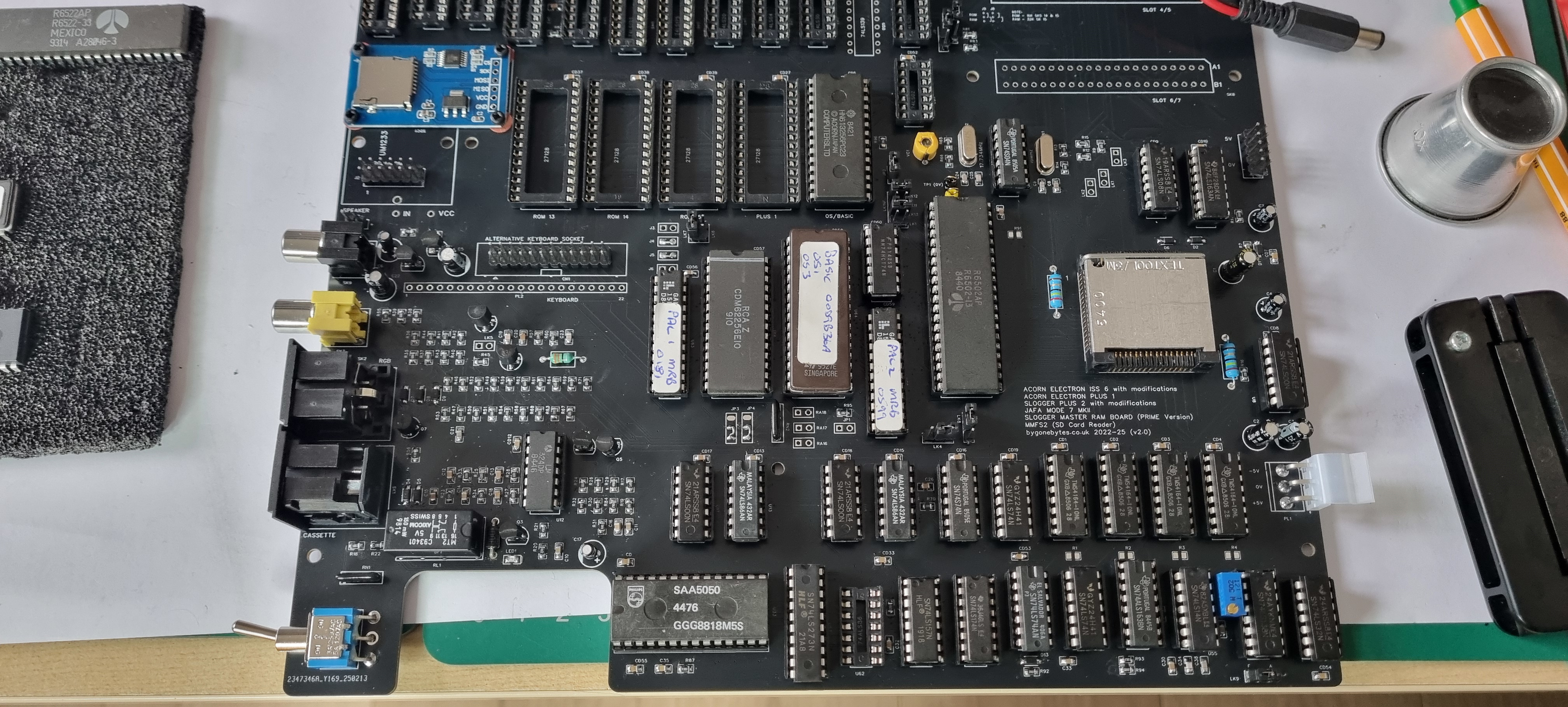
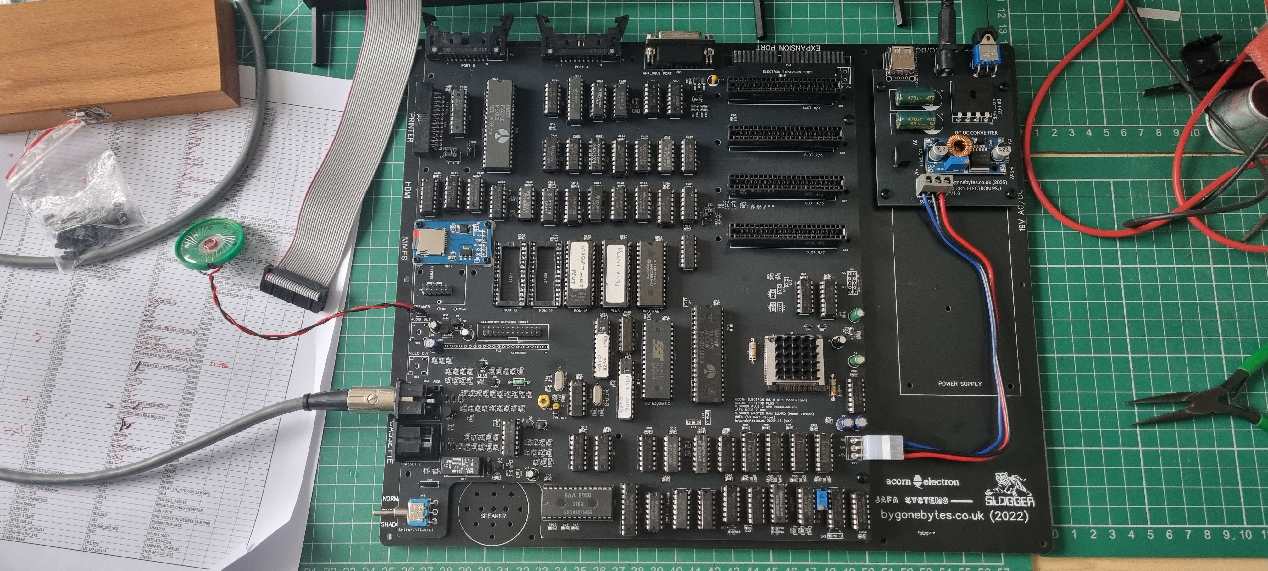
The necessary semiconductors fitted to test the basic Electron functions. I wanted to use components recovered from a broken Electron so these parts were tested as best I could, then fitted along with some new parts.
First power on and it just displays a blocky mess. This usually means that one or more RAM chips (TMS4164) are faulty. I had plenty spares but finding four that works was proving tricky so I bought a simple go/no-go tester.
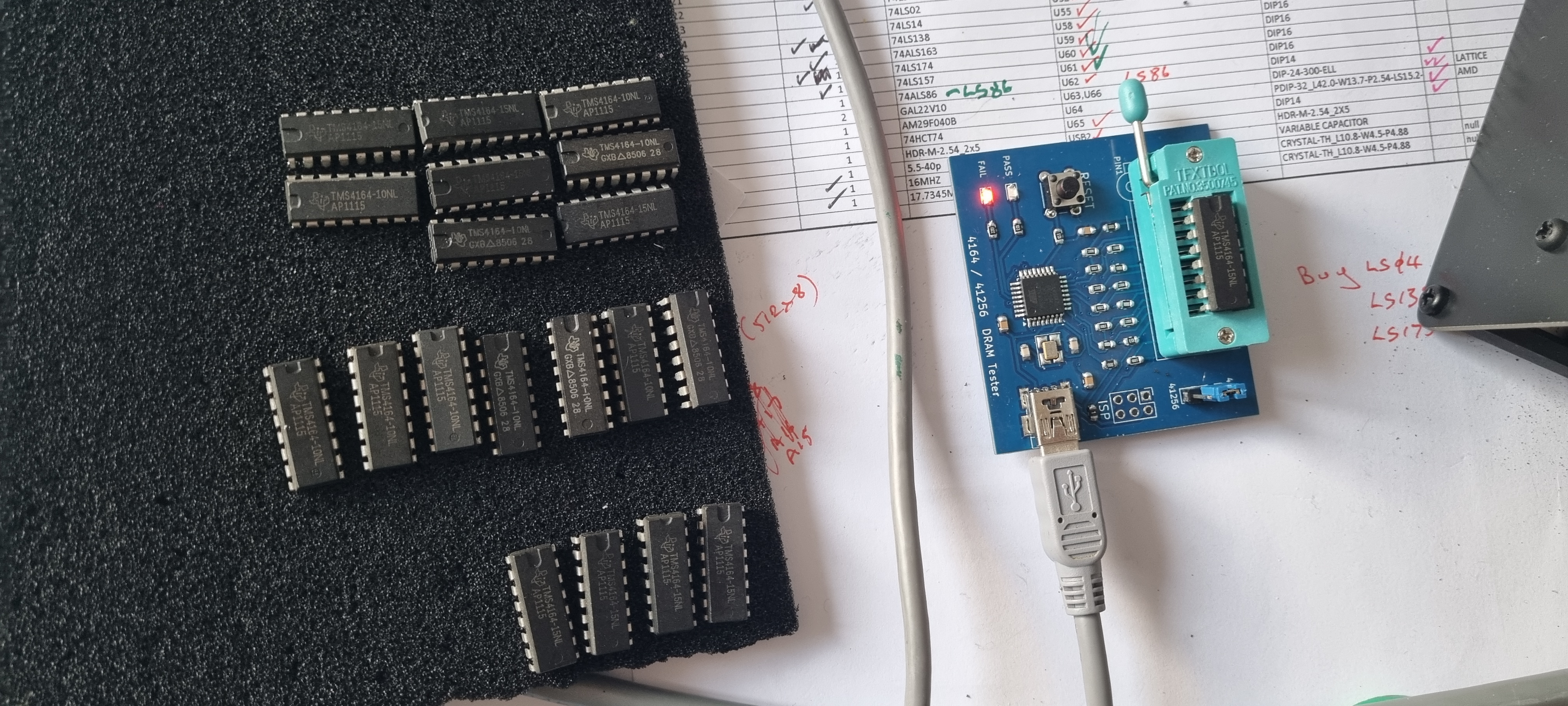
This revealed that nearly 50% of my chips were faulty. So I selected four that passed the test but still no joy, on a positive note the screen was now showing a plain white image. I re-tested the ULA in another machine and that worked so I then swapped out the processor and hey presto it's up and running.
All three modes, Normal, Turbo and Shadow were working fine so I completed the assembly ready to test MODE 7 and all the ports including the MMFS.
Testing the four catridge slots with a couple of catridges then enabling the SD card slot and testing that with MMFS2. All ok so far..
Mode 7 didn't work first time as I had run out of the 74ALS86 IC's which is required for the high input impedence for a RC (timing) circuit on one of its gates. I substituted with a 74LS86 but this just does not work. Once replaced it works perfectly.
Hindsight
I didn't pay enough attention to the new MRB design when incorporating it into the clone and I could've saved a bit of space on the board by omitting the original OS ROM socket and quite a few links. The new MRB was designed for flexibilty, by using a 29F040 with links it allows for four different sets of OS, BASIC etc. I only need one set of OS ROMs so a 27C010 or equivalent is all I need and thus would save quite a few links.
I noticed that the RAM tester also tested TMM41256 RAM IC's so I looked at the data sheet of both the 4164 and 41256 (also the TMS4256) and the only difference between the two is pin 1 is a NC on the 4164 and A8 on the 41256. A simple mode of adding a pull up resistor on pin 1 would make both IC's compatible.
This would tidy up the board a good bit and make the RAM selection more flexible.. I feel another up-tick in version number coming soon.
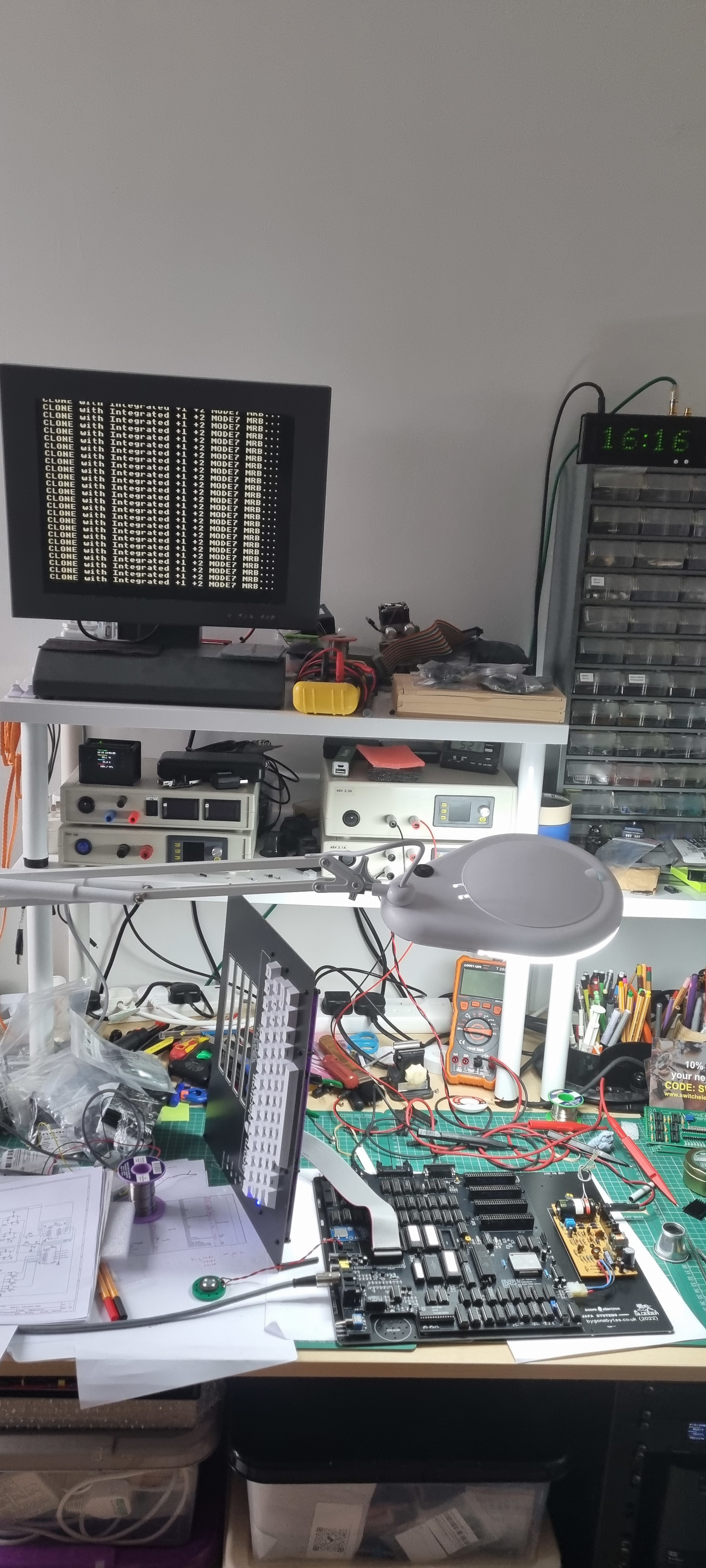
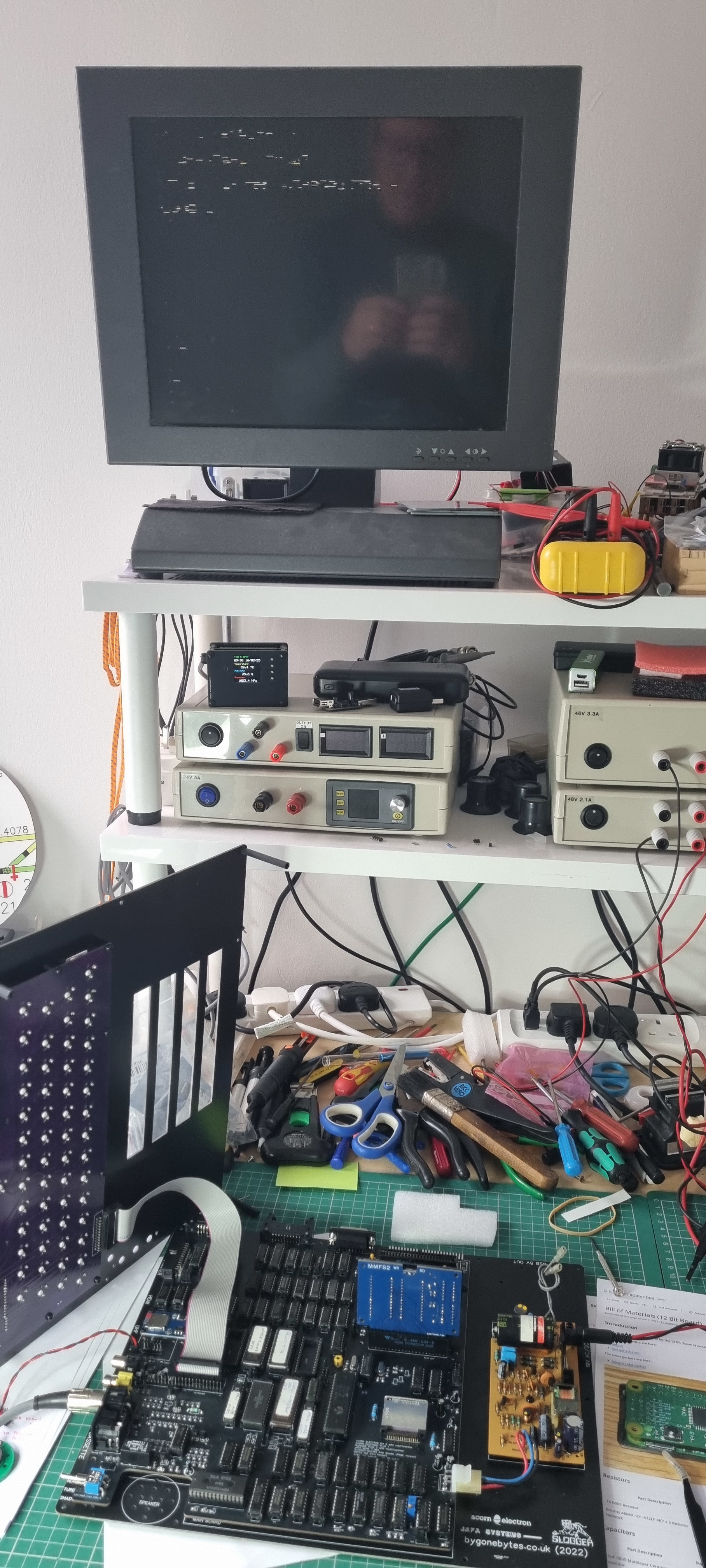
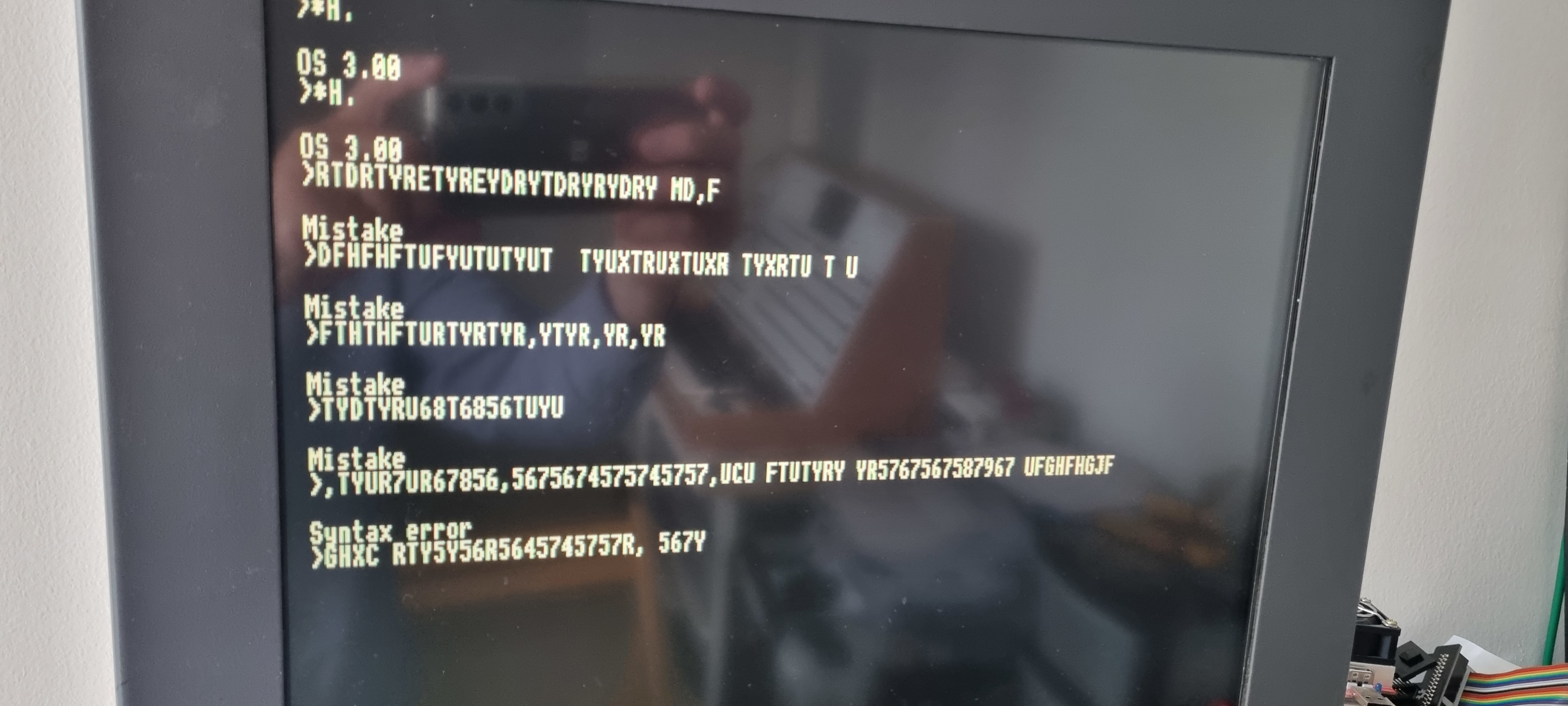
I had finished testing all the ports and as a final check I went through each screen mode to check the image quality and I found this on the 80 column modes 0 and 3:
The quality is good on power up but over a minute or so it starts to show artefacts as can be seen above. I have checked out every possible component it could have been and I now suspect it to be the ULA socket - There was an instance when the artefacts grew into white bars. It was a new socket but before I soldered it in I had to straighten a couple of pins on the ULA side..could this be the problem? I checked the ULA in another Electron and it's OK. I should now replace the socket but as it's quite an expensive part and also I was thinking I should re-doing the board as mentioned above, I'm going to delay things until I get the new board.
Clone v2.1
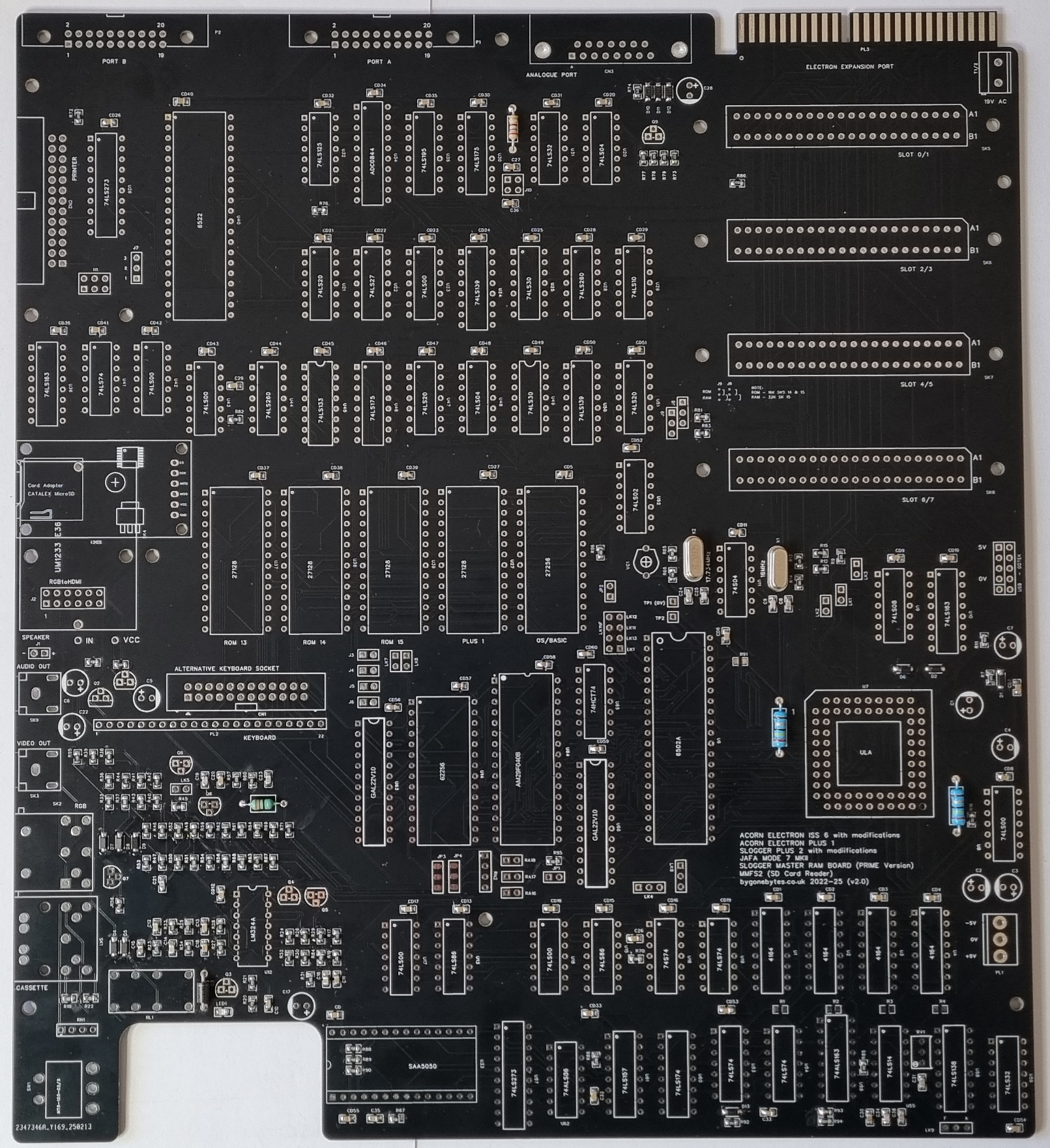
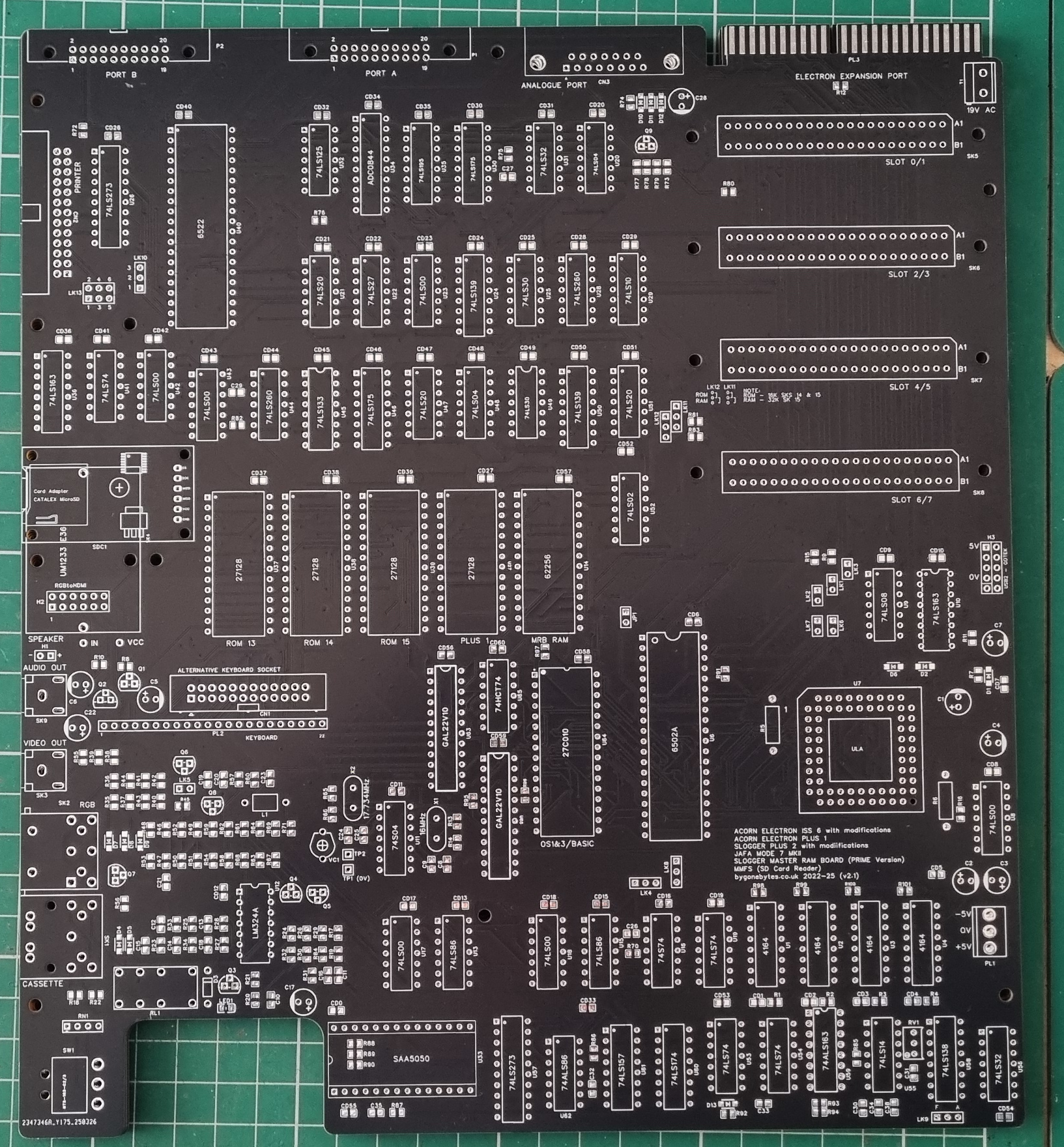
The design and layout of the board has had a good going over with the removal of the original OS socket and many of the links. I have also spent a lot of time checking the routing and spacing of the board tracking and once again I have shifted the oscillator circuits. I almost removed the entire composite video and tape circuits but left them in. The positioning of the oscillators are better when they are kept to the centre or left of the circuit board as one oscillator runs to the left for the composite video and the other to the right for the 6502 keeping them as segregated as possible.
I also added in the mod to make higher capacity memory chips compatible, not more memory available just compatible so more options on purchasing parts is possible. Here is v2.1:
I'll be building this one with the bare minimum to get the Electron up and running and soaking before I build on the Plus 1 and 2.
The basic Electron built ready to transfer the semiconductors over.
The Electron ready to switch on.
And after a good long soak the MODE 0 is normal. Good news..
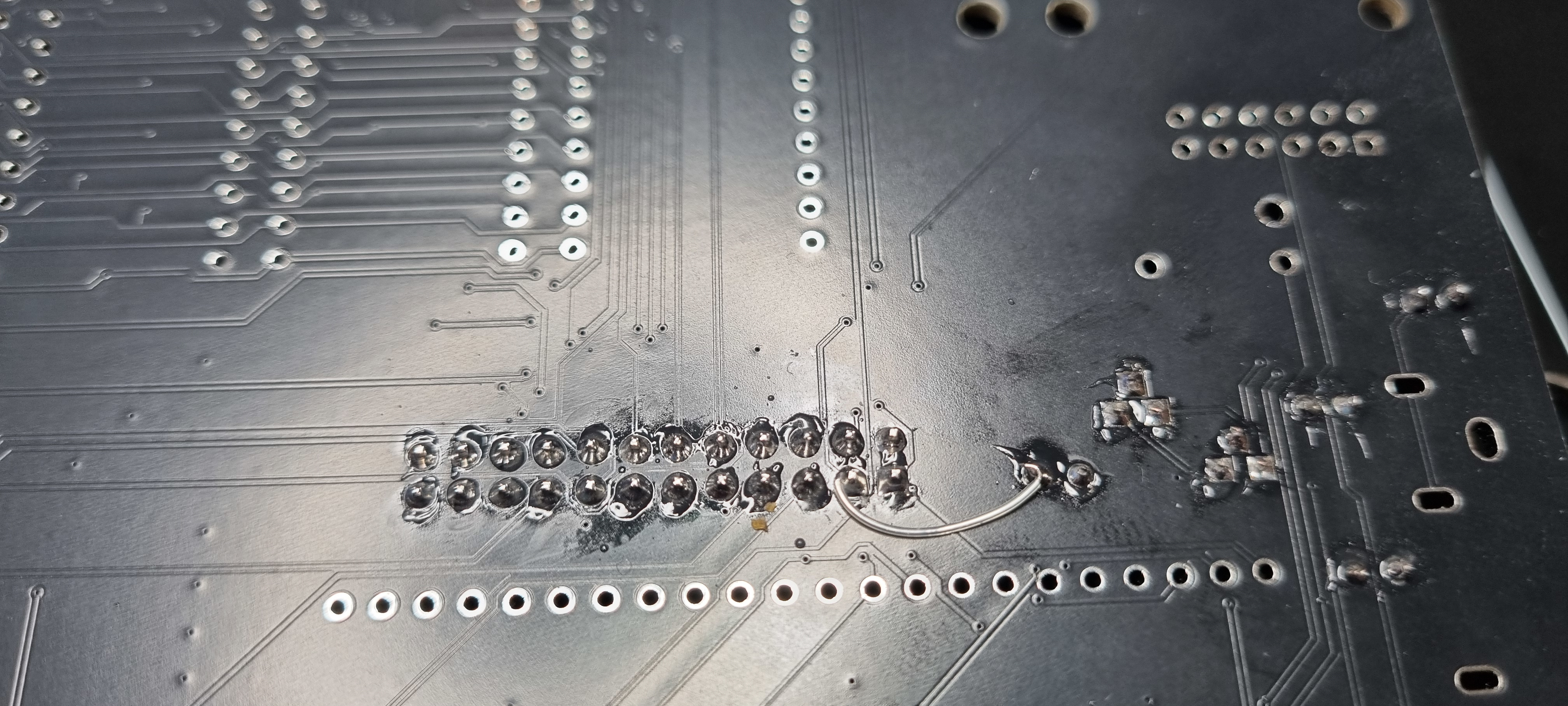
BUT !! I did find an error on the board. Between designing v2 and v2.1 the CAD program had been updated and it handled the Ground/0V/VDD nets differently so I had to go through all the ground parts and labels to make them all the same and I missed a couple which were left at 0V. A small wire loop on the underside of the board fixed this. I see the PCB need a good clean to remove the flux.
The symptoms were very obvious - the BREAK key didn't work.
Building the PLUS 1 on now.
and now the PLUS 2.
then the MMFS card reader board.
and the RGBtoHDMI.
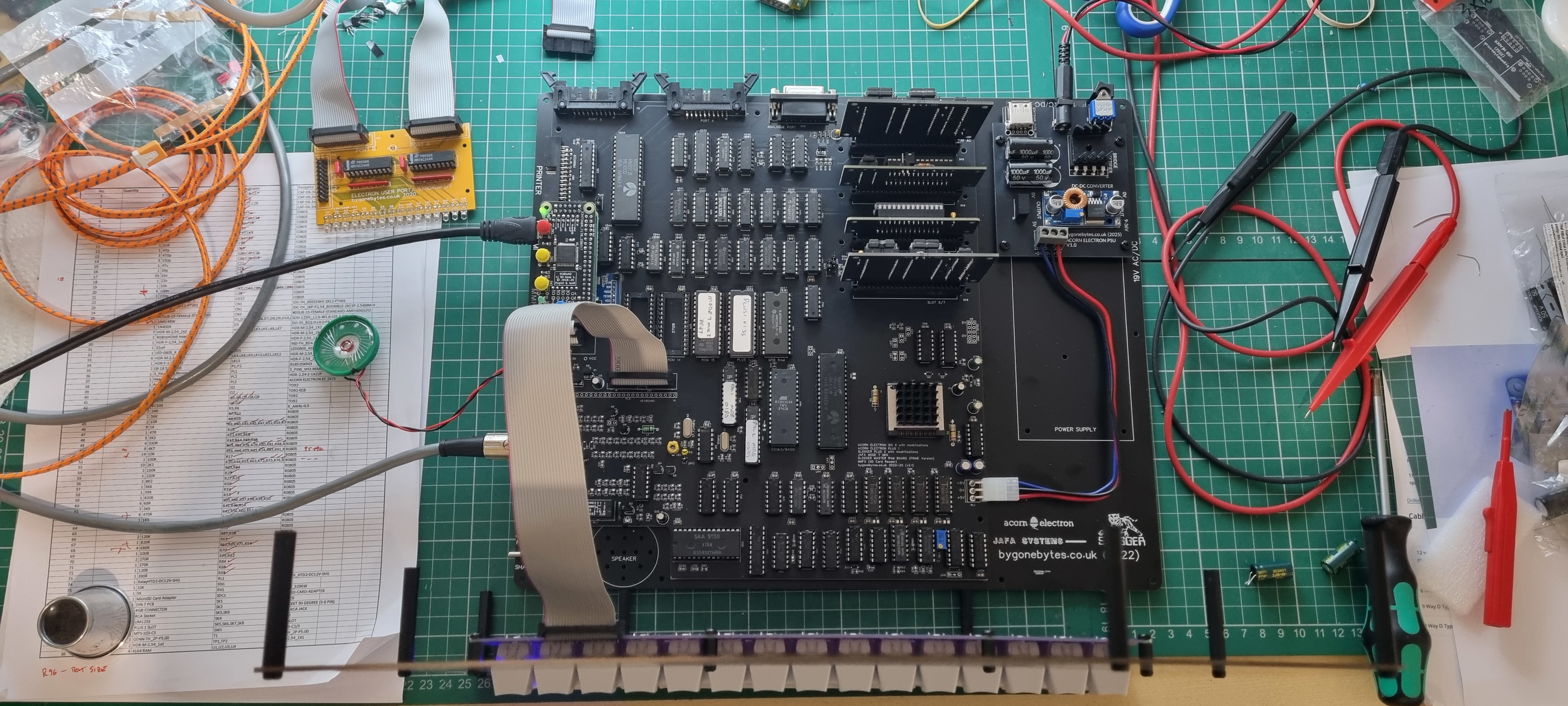
and finally setting up Mode 7.
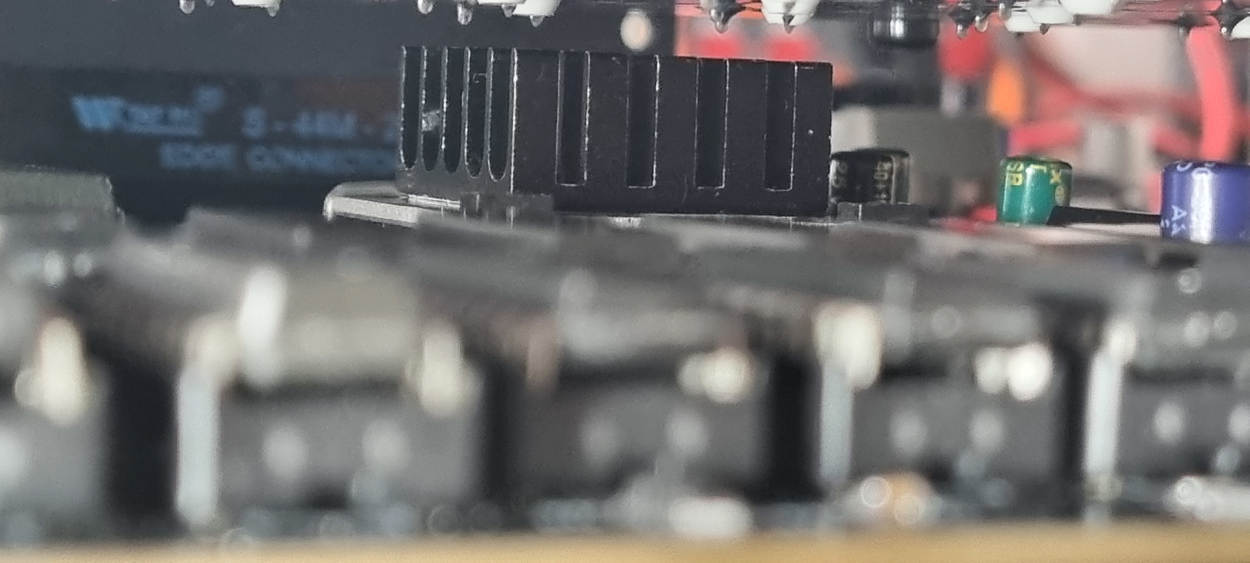
This ULA runs a bit hot so I stuck on a heatsink. The only one I had was 10mm tall so the overall depth of the machine has been increased to 40mm. Still 5mm thinner than the previous version but I'll look for a 5mm high heatsink so I can reduce it back to 35mm.
Time to glue on the speaker and close up the lid.
I am not going to get new boards with the correction but I have updated the design and the Gerber files just in case I end up going back to this project at some time in the future to make a v3..