It's been five years since I stopped working on my Maplin 5600 Synthesiser, I had got to the point where I needed to fit a keyboard but the original parts were not surpisingly unavailable. To get round this I built small circuit boards and spaced micro switches at the same spacing as a standard sized keyboard. This worked well for testing and at that point I ran out of steam on the project and I moved on to other things.
I always had this idea that I could use an old Yamaha or similar keyboard to simply overlay the microswitches and so every now and then I would look on the second hand sales web sites for cheap broken keyboads. Unfortunately most machines like this also have damaged or written on keys. A few months ago I came across an old Yamaha PSR27 which fitted the bill.
So here it is..

On the outside it looks very clean..ideal.

Undoing a lot of screws..

reveals some cobwebs and a lot of grime..

Having given it a good clean the keybed looks easy to remove. The case has markings that place the manufacturing date of 26/09/1988 and September 1989 for the assembly date.


Keybed removed and is looking good.


I was pleasantly surprised to see a very simple diode matix incorporated on the frame so I did a quick check and scribbled out some of the circuit. I can definitely drop the idea of using my microswitches.


From this I have a few options. I could try and interface it directly onto the existing Binary Encoder or I could use a Raspberry Pi Pico to replace the encoder completely.


The original binary encoder relies on single pole change over key contacts but this keyboard has single pole 'contacts'. I am looking at re-using the diodes in a different configuration - not sure if the above will work or I could use the existing diode matrix and scan it from the GPIO of a Raspberry Pi Pico and output the relevant codes to entirely replace the encoder.
decisions, decisions..

I decided I'd have a go at using a Pi Pico to emulate the binary encoder as it is the least invasive to the keyboard and it's also a good challenge in programming. To this end I completed the reverse engineering of the diode matrix and it seems easy enough to interface to a Pico.

My first version of the code conversion list.
Whilst working out the necessary coding conversion I thought about the physical interface. Luckily the ribbon cable connector on the circuit board has a similar layout to a 15 pin 'D' type connector so I will be able to solder that in place without removing the circuit board then I'll run a ribbon cable to the Pico test breadboard.
The PSR27 keyboard uses the same data for each group of six keys and each group has a common Group Select bit - basically the keys are multiplexed. My aim is to use the Raspberry Pi Pico to demuliplex the data and convert it to the 5600 key codes. It has also got me thinking about Midi but that will be much further down the line.
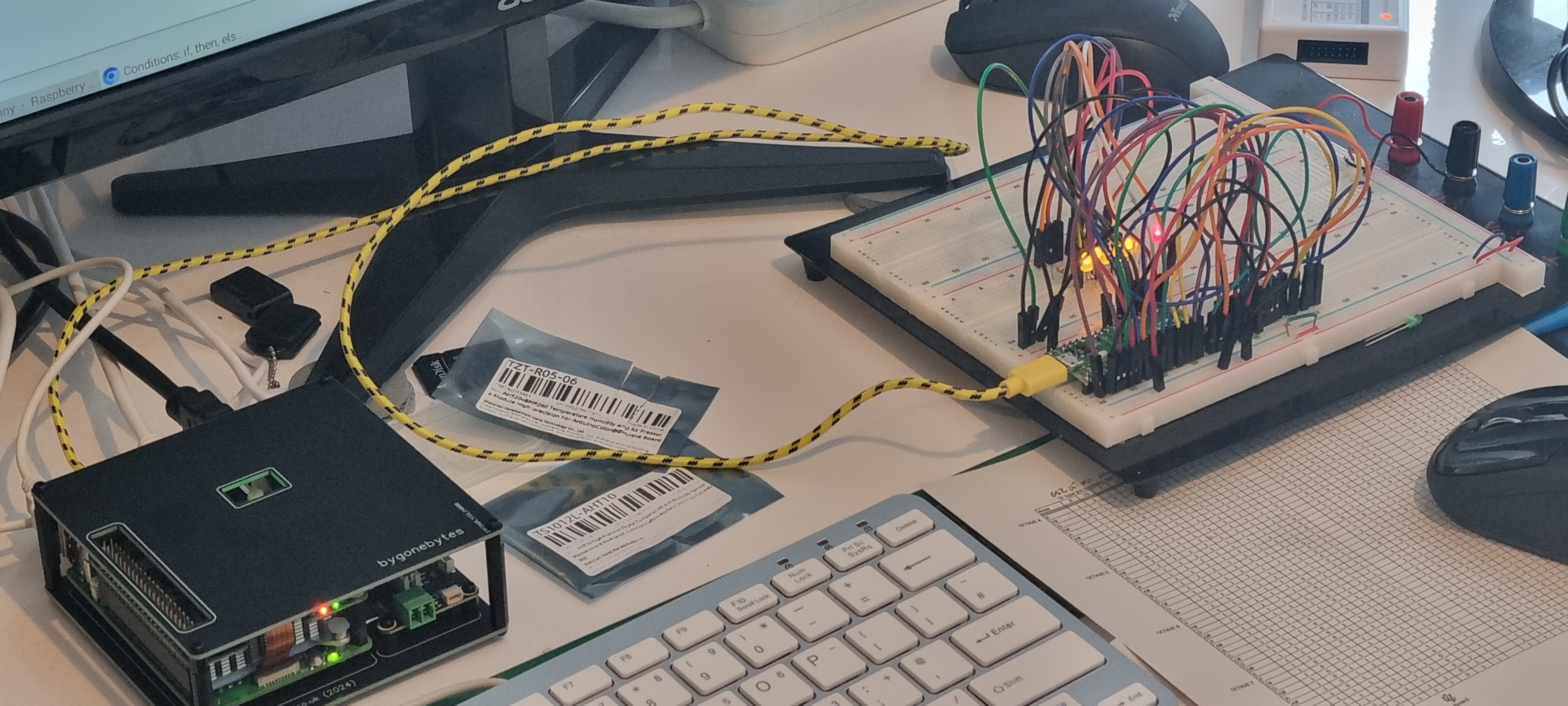
I have set up a breadboard with a Pico, some LED's and the wiring ready to connect to the keyboard. The LED's show the codes for the key presses.

I've also written this simple test program to output the key codes. It declares all the I/O required and sets the outputs to a known value. It then scans the keyboard diode matrix asserting a logic '0' on each row one at a time and reads the columns in as data each time. At the moment it just passes the data straight out to light some LED's so I can see what is going on. Once I've tested this with the keyboard I'll write the code to read each key and convert the data to what the 5600 expects.

I have moved the breadboard over to my other bench closer to the keyboard ready to connect it when the parts arrive. The Pico is connected to the RPi via a USB extension to make it easy to do alterations to the software.

The parts arrived and it didn't take long for me to abandon the 'D' type idea. It would be very tricky to solder on and once a connecter is plugged in it would be too tall for the keyboard to sit stable on the bench (or in the synth). I basically made the mistake of removing the original ribbon cable from the wrong end - I should have left it connected to the keyboard then I could have simply crimped some dupont connectors on. I made more work for myself!
So the next idea is to solder in some ribbon cable terminated in dupont connectors. To do this I have to do something I was trying to avoid and that is to remove the key PCB and the connector.


Key PCB and connector removed.


And soldering in the new ribbon cable.

Refitting the key PCB

and bringing the ribbon cable out the back ready to connect to the breadboard.

Jumper wires used to connect to the breadboard and I'm now ready to test.

I checked each key to ensure the correct code appeared. All good so far..
It was at this time I noticed something so obvious I don't know how I missed it - the first note on the Maplin Keyboard is an F and this is what I based version 1 of the keyboard conversion table on but the new keyboard starts at C.

Comparing keyboard layouts.

I've updated the table and for the moment I have decided to start the conversion based on the Maplin 61 note keyboard. See fig.4 and table 1 in the Maplin Contruction booklet.
Now on with some programming and designing an interface.

I cribbed a bit from the original binary encoder and added some level shifters between the Pico and the 4000 series monostables and made up a PCB.

When considering how to power the Pico I looked at the Synths PSU, the 14V rail only has a 300mA capacity and the 5V, 60mA. Neither of them may be able to cope with an additional 50mA. To give me some options I added a 5V regulator onto my board so it could be powered from either the 14V or the unregulated 20V.

Time to get the Synthesiser out of storage.

Unpacked and on the bench.

With some trepidation I switched on the sequencer first, I needed to check if the SD card and the program had survived..it had! So I removed it and took an image file so I could retain a full backup including Python 2.7. Next I switched on the synth and after plugging in a few patches I managed to get a sound out of it. So far so good.


Building the PCB ready to install in the Synth.

Checking out what I need to remove.

The board installed and the start of testing.

A few mods later and it is basically working but there is still a few niggles I need to iron out.
The most important fix I have to make is this: The original keyboard encoder allows a key to remain pressed while pressing another key above or below it, my scanned keyboard will only allow a key further up the keyboard than the key that is held pressed and not below. This is a issue with the way I scan the keys i.e. from top to bottom, the scan will play the first key press it sees which will always be that key or above. Some more thought will need to go into this. At this stage I'm also thinking about an alternative solution to interface the keyboard directly to the original keyboard encoder.
A little research later and I have found there are at least three different key or note priorties for monophonic keyboards, last note priority, low note priority and high note priority. This keyboard will be last note/high note priority where if you hold down C4 then press and release G4 you'll hear C4,G4,C4 etc. If you press a low note it will not play.
Earlier on I had to make the decision on what octaves to program the keyboard with (C3 to C7) but while I was waiting on some circuit boards to arrive I thought I could make it easily switchable between C3-C7 and C4-C8 so I've added this little feature.
I'm just waiting on an updated version of the PCB to arrive...normally the boards arrive within six days from posting, it is now twelve and counting. About six of those days my PCB's have been sitting in London! patience..
The boards finally arrived and I built one with just the components needed. I decided to power the board from the synths 14V supply so I included the 78L05 regulator and the link. I didn't add the LED's for three reasons, they won't be seen, they use precious current and I really only put them there for testing/debugging.

Before plugging in the Pico and CMOS chips I checked the 5 and 14 volts are going to all the right places.

Then with the PCB fully loaded I checked the current it was drawing, approximately 27mA. (With the LED's this would have peaked at 35mA)

At the moment I'm not sure which side of the keyboard to fit the octave select switch. At the moment it is on the right hand side but I could add it to the panel on the left.

Now I need to measure up to fit the keybed in place.

The keyboard is now fitted and the octave select switch is mounted on the panel to the left just above the joystick.

The new keyboard encoder PCB is screwed to the base in the same position as the previous board. I've left the USB cable in as I still have to add the foot peddle on/off into the software.
Project is on hold (Jan 2025).
Feb. 2026 - Last year I got bogged down with a couple of glitches in both the software and hardware so I took a break from the project and now with fresh eyes I could look back over the above work and hopefully find some solutions. I found where the problems lay but having tidied away my synthesiser again I set up my original v1 PCB on the bench and started afresh with the software.
The first thing I did was to make the change from MicroPython to CircuitPython so I could use the built in keyboard module. This simplified the keyboard scanning and with a complete re-write of the output data coding I think I have managed to emulate the Binary Encoder very accurately. I also found a mistake on my first two versions of the PCB - I had put the 'KEYDOWN' signal through a monostable, why? I don't know, when from the circuit diagram it clearly comes straight out as a simple 14V level change while a key is pressed!
The Binary Encoder emulation includes the six 300uS pulsed Data outputs, the Keydown output and the Footswitch input. I have also kept my addition of the ocative switch which moves the entire keyboard up one octave. The software is ready and the PCB is in production.
This is the current circuit diagram with the Keydown signal coming through a level shifter at 14V straight to the output pin.

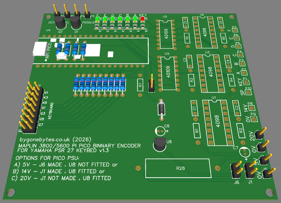
and the updated PCB
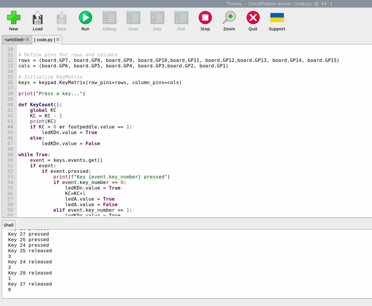
and some progress during programming.. It didn't take long to complete and when the new board arrives I'll get my synth out to install and test.
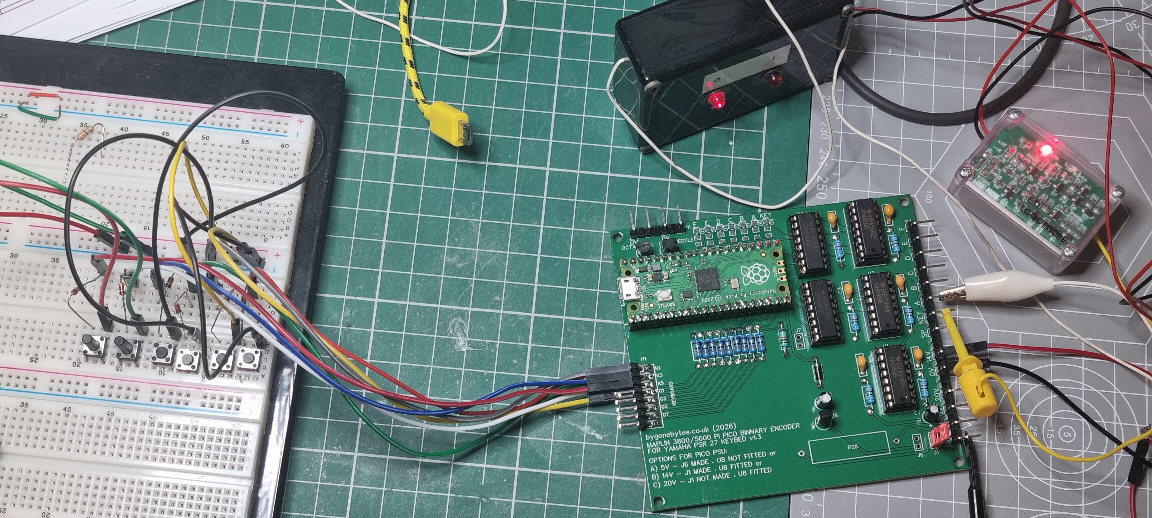
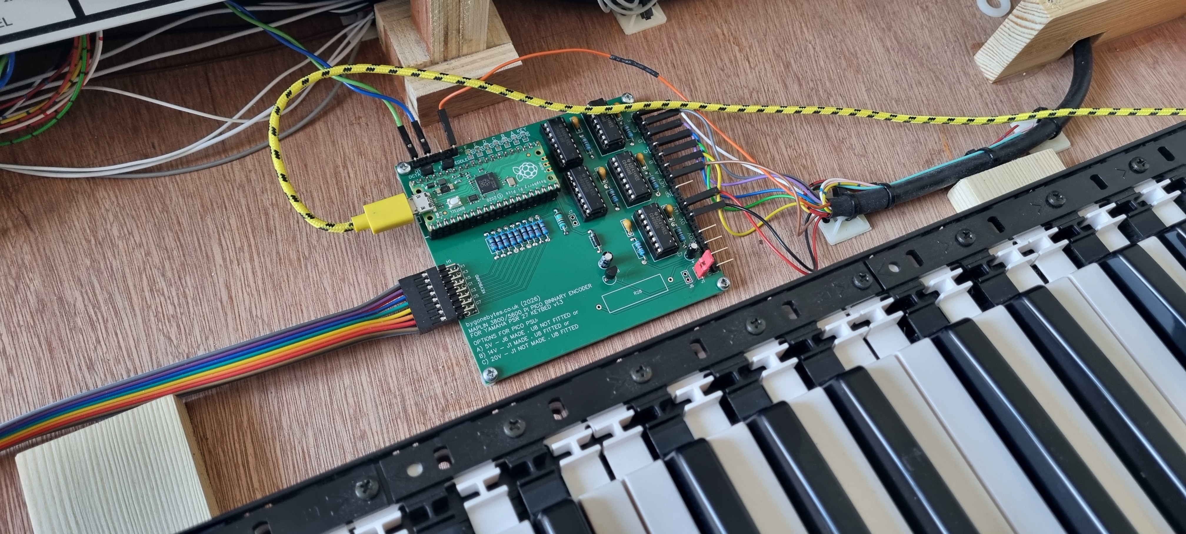
After a couple of weeks the board arrived and here it is built and being bench tested.
I looked out my synth and removed the v1.2 interface board and replaced it with this one.
After checking all the key codes are correct for both octave switch positions I am pleased to say that it works 100%. I can now complete my build by finishing the case, just two pieces of plywood should cover the back of the keys up to the fascia and a fill in piece at the right hand side.
Job done after just 8 years!! At the bottom of this page is a zip file containing the Gerber files for the PCB, the circuit diagram, the Bill of Materials, my code.py, the circuitpython UF2 file and the key conversion sheet.
How the program works:
The program is much simplified now that I'm using the CircuitPython Keyboard module so there is not a lot to it, just a few building blocks - Importing modules, declaring I/O, keeping track of key presses and the main loop to detect the key presses & outputing of the note data. Here is my description on how it works:

Bring in the required modules - board, keypad and digitalio.

Next I define the output pins. The first six are the Binary Encoder outputs, A to F as labelled in the Maplin 5600 construction booklet. The last outout, KDn, is to replicate KEYDOWN output.
There are two inputs, the first is for the footswitch, pin 11 on the original encoder design and this replicates a keydown when the footswitch is pressed. The other input is for the 'Octave' switch which moves the notes on the whole keyboard up one octave when toggled.
Now I declare a variable KC which will store the number of keys that are pressed. This is used to ensure the Keydown output does not go low until the last key is released.

The next item is to tell the keypad module the row and column GPIO I'm using for the keyboard matrix and then to initialise it.

My one and only function definition - this determines the output state of the Keydown output and is checked whenever a key is released. The Keydown only goes low on the last key release or if the footswitch is not pressed.
A key press increments the KC count and this function decrements the KC count on the release of a key therefore if the count is 0 it knows there are no keys pressed and puts the Keydown output low only if the footswitch is not pressed.

The main loop - this loop checks for a key press and returns a key pressed or released number, in this case between 5 and 53. It then checks what to do with that key press or release. For instance if the first key (key 5) is pressed it outputs a KEYDOWN, increments the key count (KC) then depending the postion of the Octave switch outputs the key value to the outputs, A through F, to the circuit board monostables which produce the 300uS pulsed output for the keyboard controller.

When the key is released the event runs the keycount function which is described above.
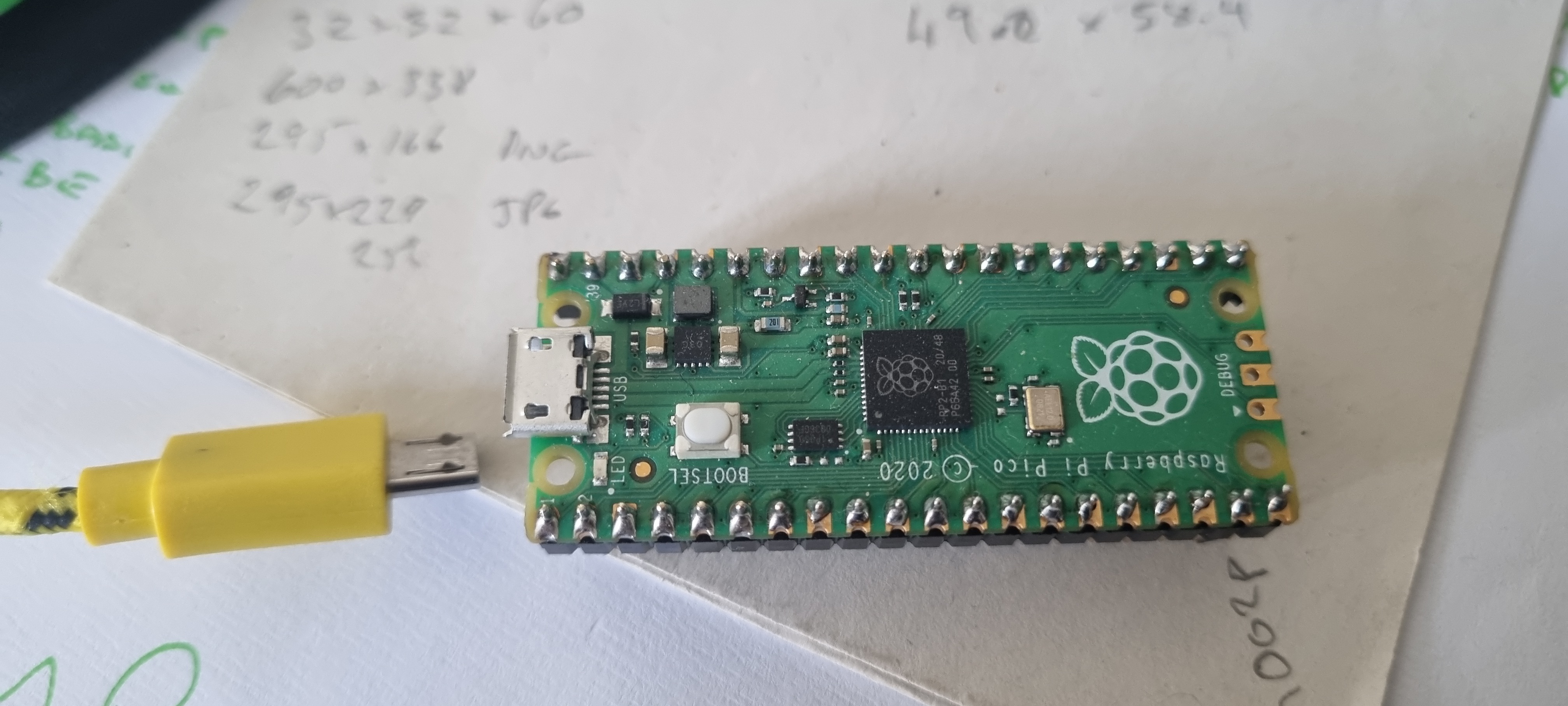
Preparing the Raspberry Pi Pico.
The preparation is fairly straight forward, first unzip the files, adafruit-circuitpython-raspberry_pi_pico-en_GB-10.0.3.uf2 and code.py from the above zip file into a suitable directory on your PC, Mac or Raspberry Pi. I used a Pi 500+ for this.
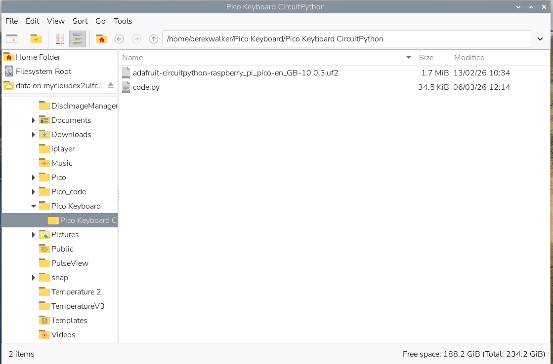
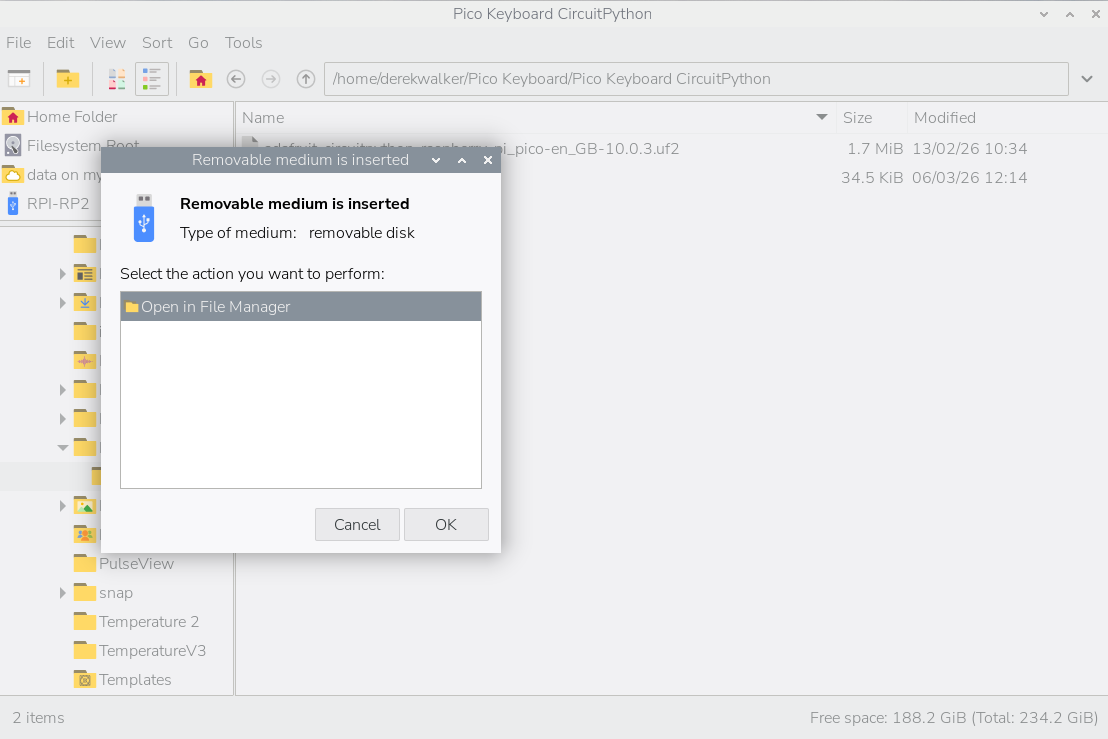
Then get a USB cable ready to plug between your computer and Pi Pico. With the cable connected at the computer hold down the white button on the Pico and plug in the Pico. Keep the button pressed until you see a window open that asks what to do with this removable media.
Clicking OK will open a folder on the Pico.
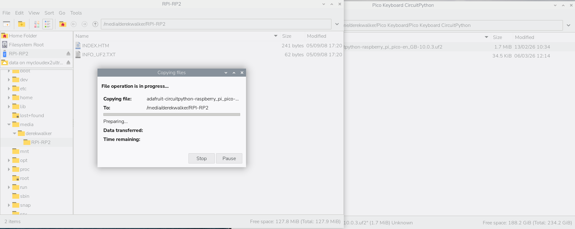
Then with these windows open drag the file, adafruit-circuitpython-raspberry_pi_pico-en_GB-10.0.3.uf2 onto the Pico folder. After the copy completes the Pico window will disappear and shortly after a new window/folder will open.
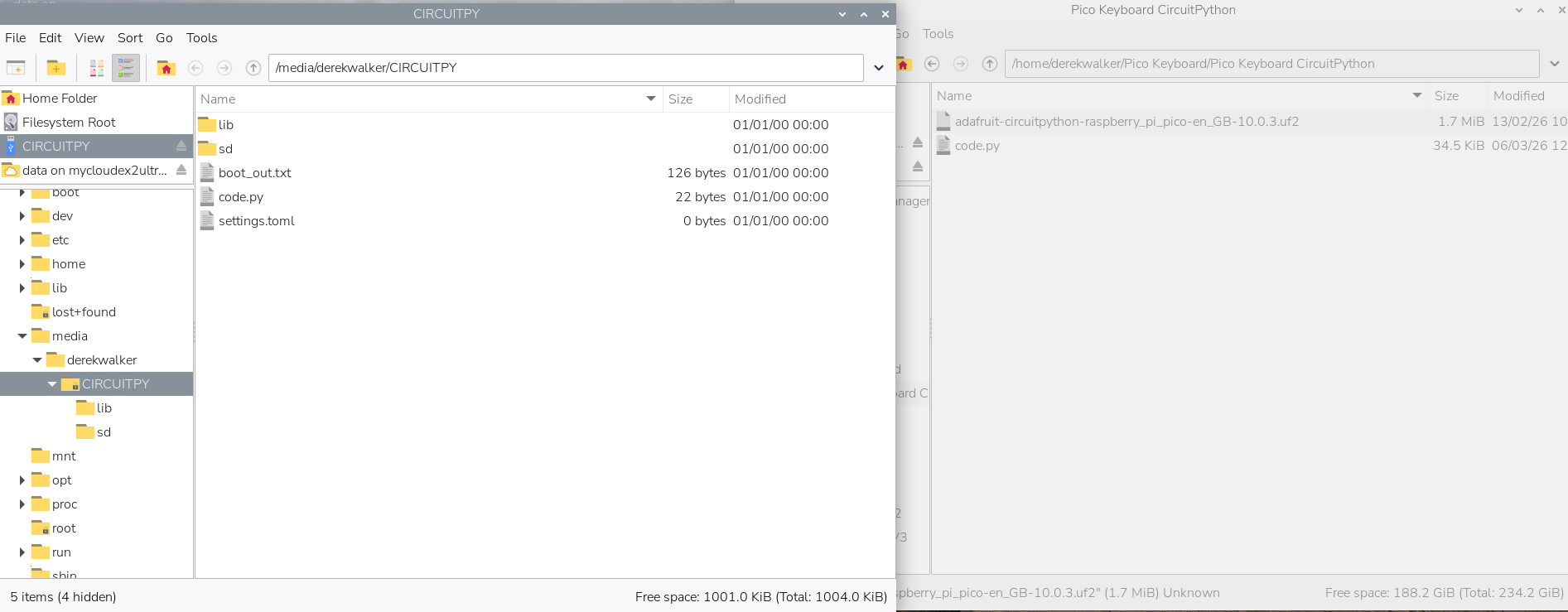
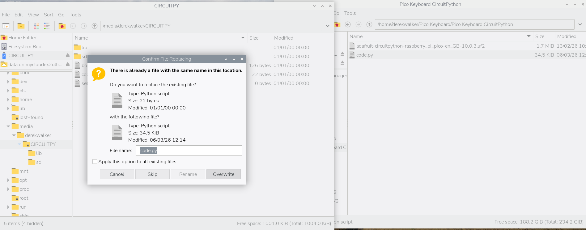
Next copy the Binary Encoder program, code.py, onto the Pico which will overwrite the existing example file.
When the copy is complete unplug the Pico and plug it back in again - the onboard led should flash about four times and that's the program running. Once plugged into the Binary Encoder PCB and powered up the programme will automatically run.