Introduction
This simple checker for the GAL 22V10 and 16V8 is more or less just a switch & LED board. It has a ZIF socket, LED's for all Input & Output pins and switches for each input. Links are used to set the direction for pins that can be assigned as Inputs or Outputs.The idea is that a programmed GAL is placed the ZIF socket. With power applied inputs can be set using the switches according to the equations, LED's showing ON for '1' and OFF for '0', and the outputs will then be seen changing, again LED's showing ON for '1' and OFF for '0', and can be checked against the expected pattern.
I get away with this simple input circuit as the volt drop across the blue LED's are greater than 2.5V, 2V and above is a logic '1' on a GAL chip.
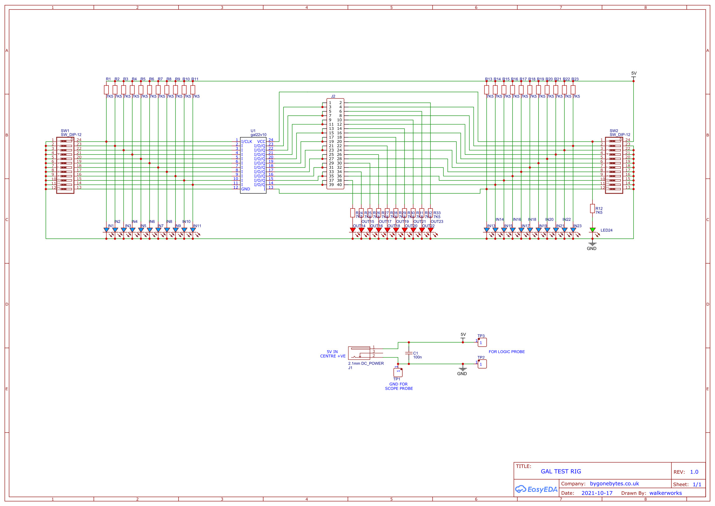
Schematic.

PCB layout.
As the board is quite dense in resistors and LED's and I had a discount voucher I used the JLCPCB assembly service for this board. It will make for a better and more consistant placement of components.

And a nice and neat job JLCPCB made of it.


Assembling the rest of the PCB and testing my newly programmed GAL for the ROM/User Port cartridge.

And final assembly onto a mounting plate so it can be hung on the wall for storage.