Introduction
I left the Electron Clone with Jafa Mode 7 MK2 PCB with a small list of corrections and extras for this update and I have also given a bit more thought to a form of case that doesn't involve as much work as the folded aluminium/painted case I made for first version.Version 1.2
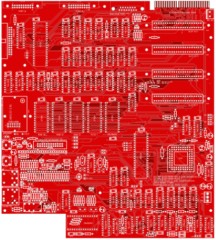
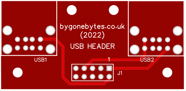
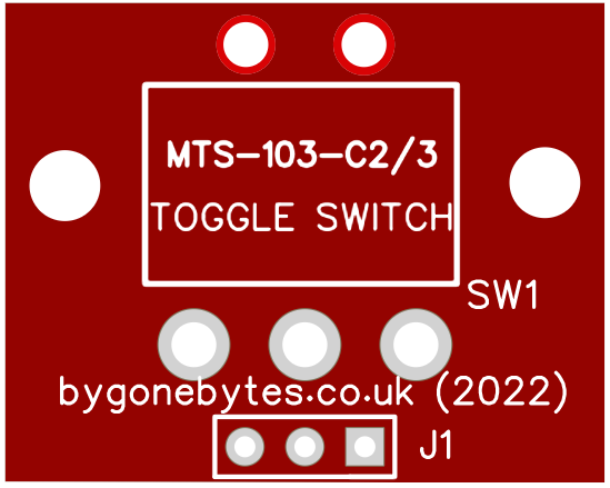
This version of the PCB will be red along with a couple of optional boards for the USB socket(s) and a switch for a MRB.
The changes are listed below
1) Correcting the RGB red/green error on the SAA5050
2) Fixing U28 silkscreen to read 74LS260
3) Mode 7 - change IC types and labels for U59 and U62 - ALS versions.
4) Mode 7 - change R91 to a multi-turn preset.
5) Remove IC14 - not required.
6) Remove Links 10 to 13 - not required.
7) Add mounting hole near slot 0/1 - not reliant on slot mounting holes to fix PCB to base.
8) Added USB header (power only) to power Gotek drive.
9) Added labels on LK9 - A & F for ULA type.
The Case
My original thought was to sandwich the PCB between two pieces of acrylic, it could have a range of colours even clear if you like the look of the PCB. I set about designing the top piece of acrylic using Inkscape on the PC but before long I found that Inkscape was just not reliable enough to use so after a look for a simple freeware 2d CAD package I settled on the EasyEda PCB layout designer. At first I thought it would be a bit too basic but the more I worked with it I realised that I shouldn't use acrylic just a silkscreened PCB.
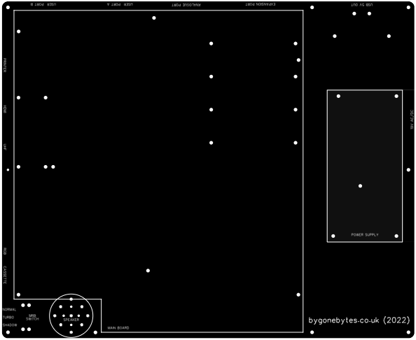
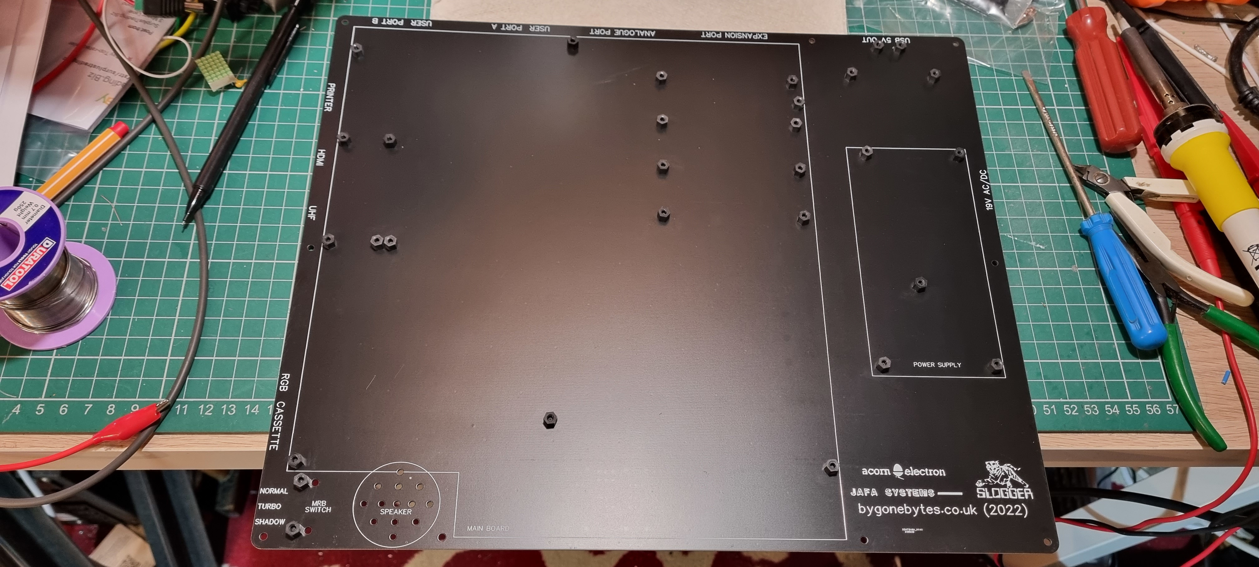
My designs so far for the top and base, the PCB's will come drilled and milled so it's a simple matter of using stand offs to mount everything.
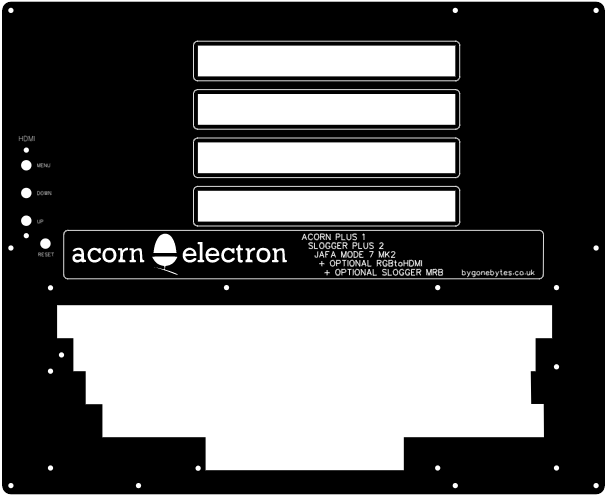
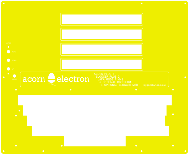
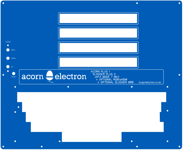
My colour of choice is black but there are other possiblities, red, green, white, purple and these..
Assembly
And running out of parts...
A pause until parts arrive, sockets, capacitors, switch, keycaps etc.
Two new small PCB's added for this build, one for up to 4 USB power outlets and the other for the MRB switch.
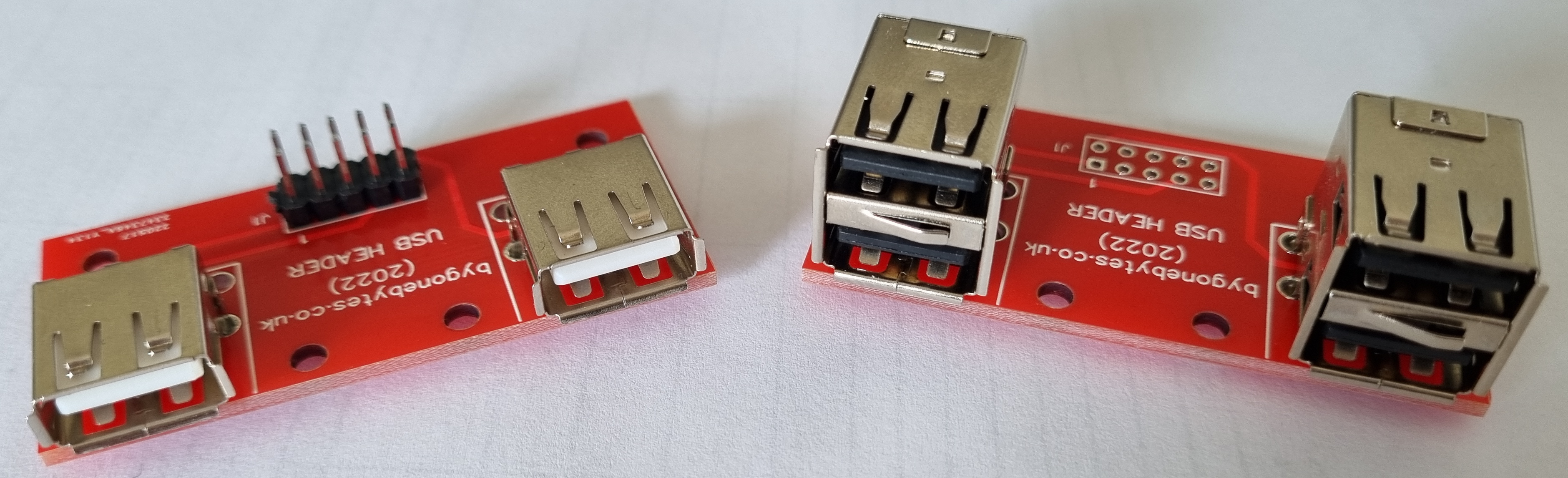
2 or 4 USB sockets.
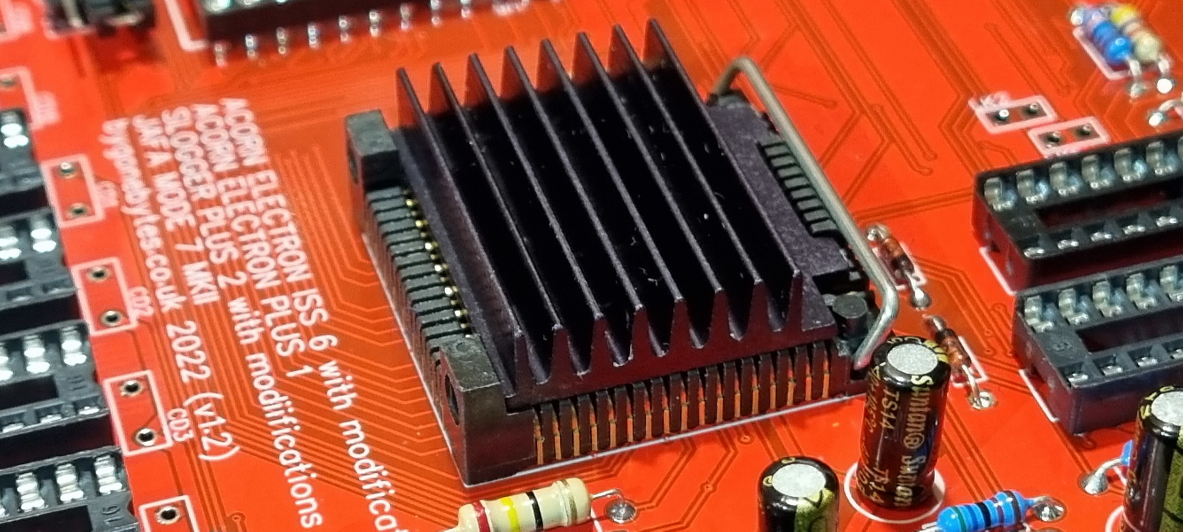
While rummaging through a box I came across this heatsink..then I recognised it's shape..its for the Electron ULA! so I'll use it on this build.
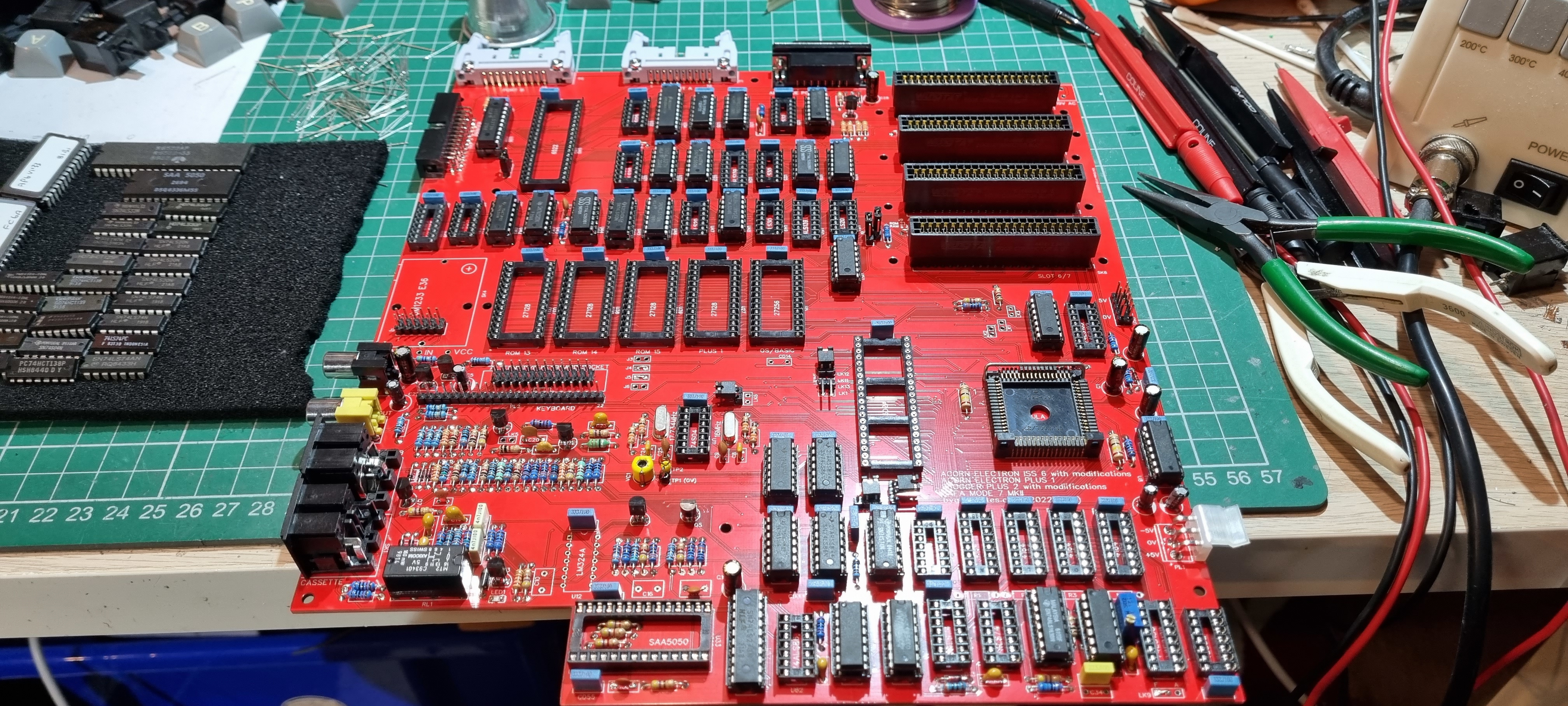
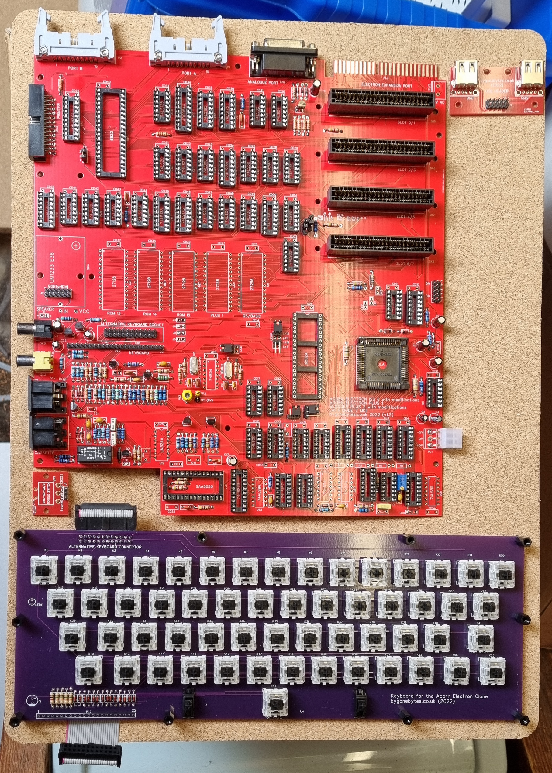
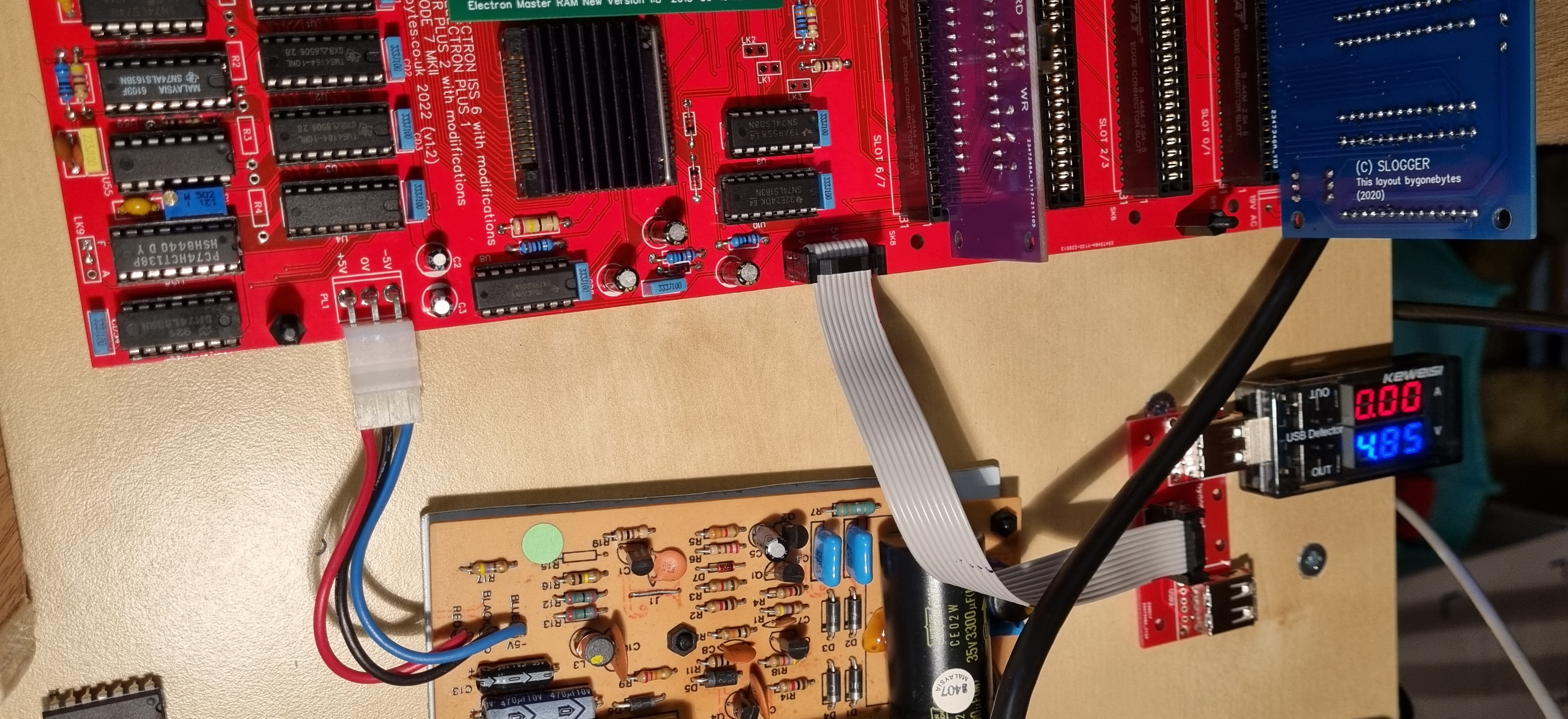
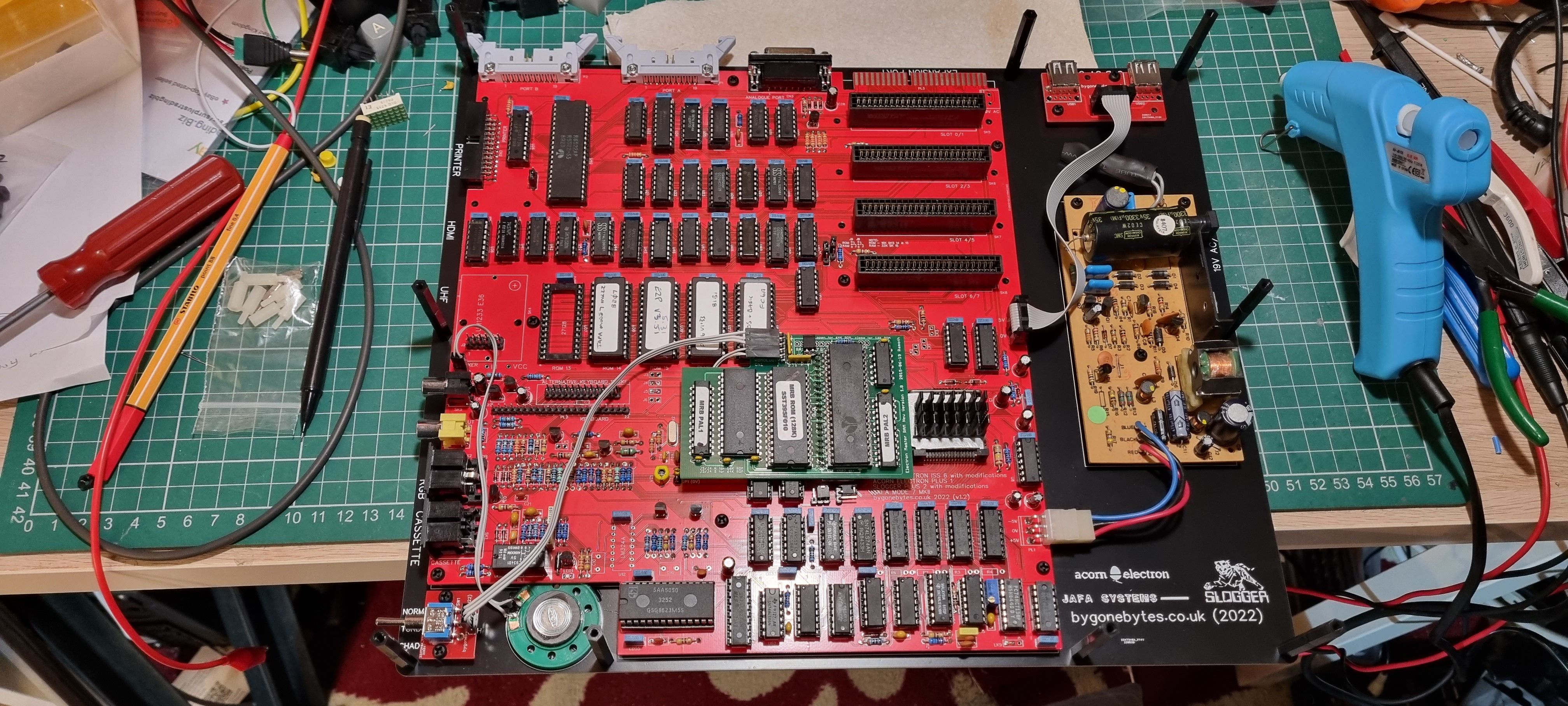
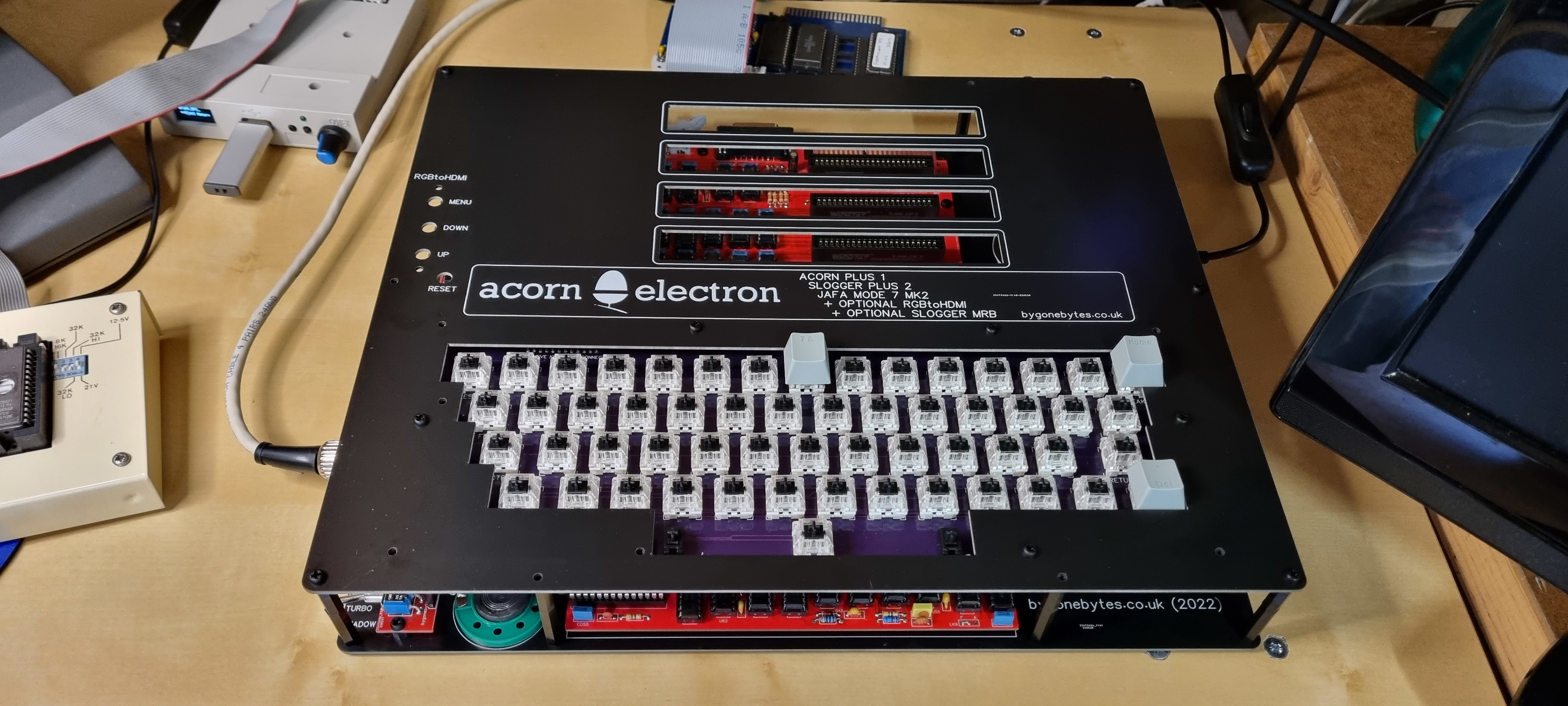
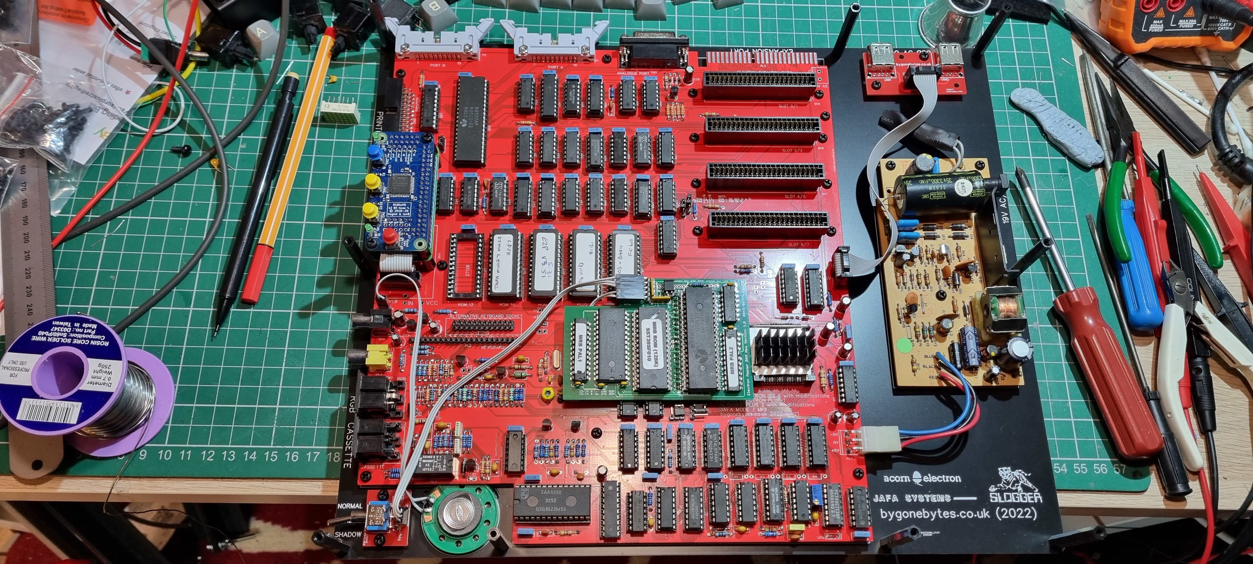
And restart - enough parts have arrived that allowed me to populate the board and start testing.
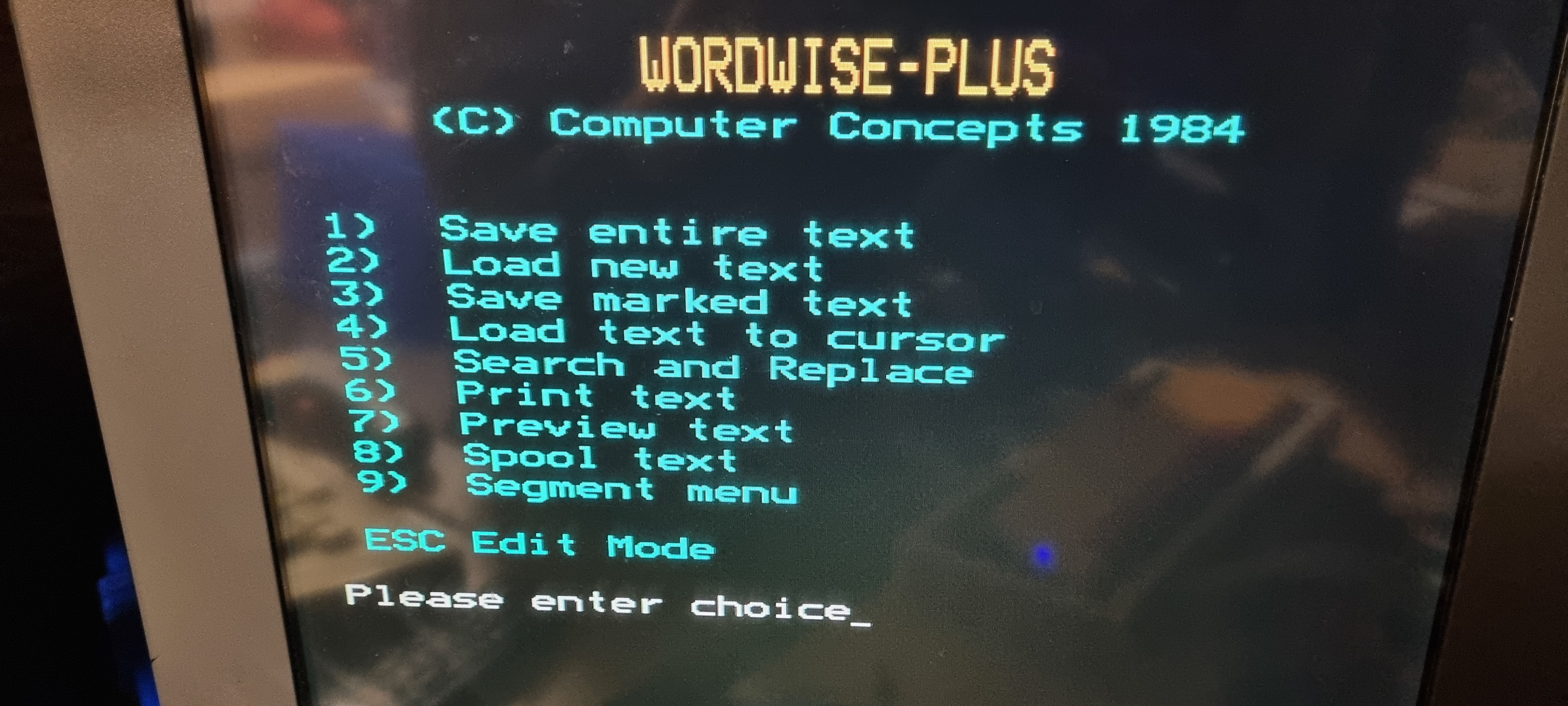
After the careful switch on of previous boards I went all in this time and populated the board with just about all of the components and switched on...it worked sort of!! I got the start up display but the text had chunks missing..I thought probably a duff RAM chip and it was.
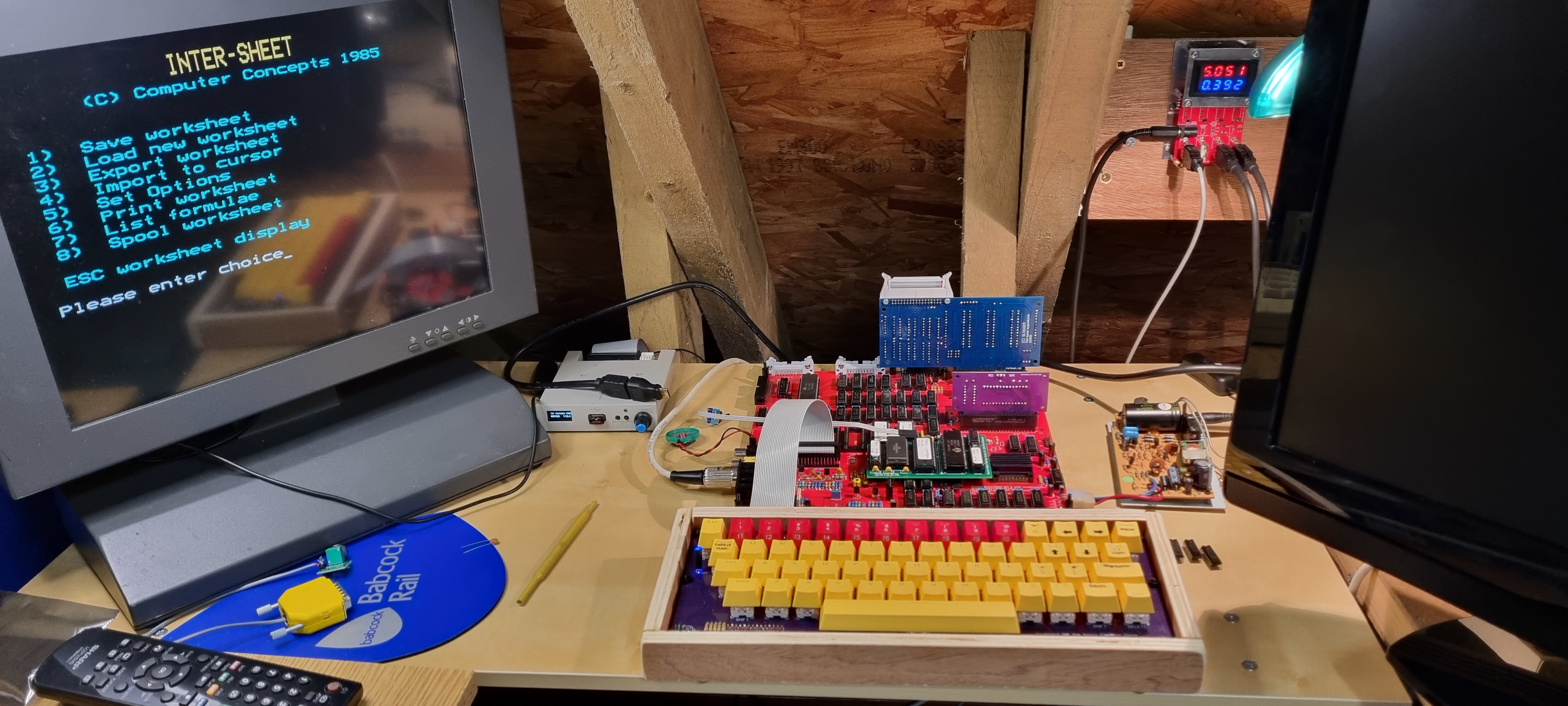
Next I tried Mode 7, I tuned the new pot and it brought in a sharp picture but with random horizontal lines the size of the cursor flicking across the screen. The problem turned out to be the 74LS32 chip in the Mode 7 circuit.
A nice crisp picture, much better than the prototype v1.1. A noticable improvement with all the superfluous tracks, links and IC removed from the PCB.
Testing the new addition of a USB power outlet.
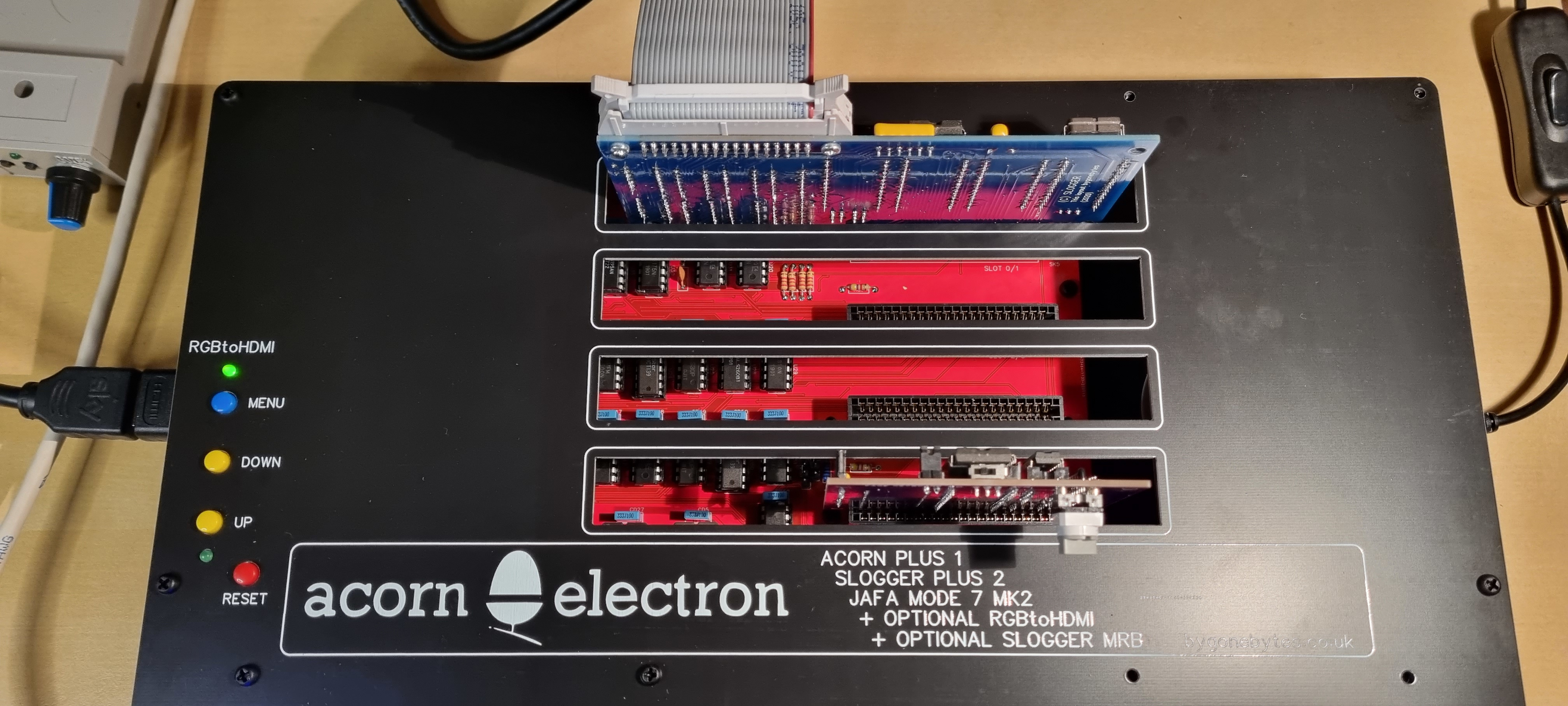
Assembling the boards into the case
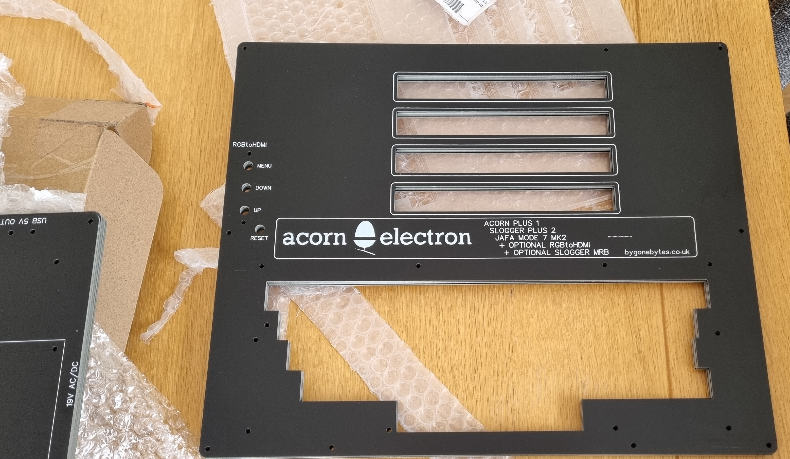
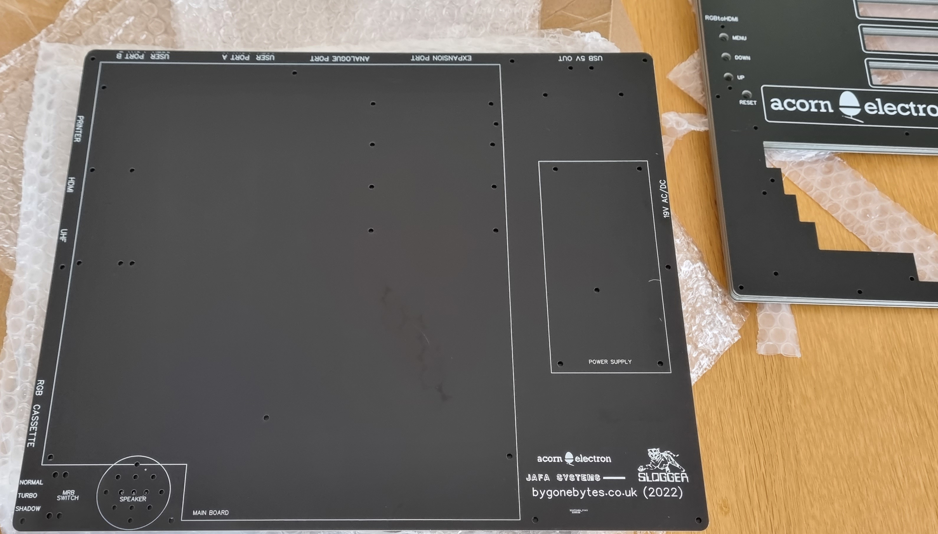
I looked at two materials for the top and base, acrylic and PCB. Both worked out more or less the same cost so I decided to use the PCB as it was much easier to place the holes and to include legends.
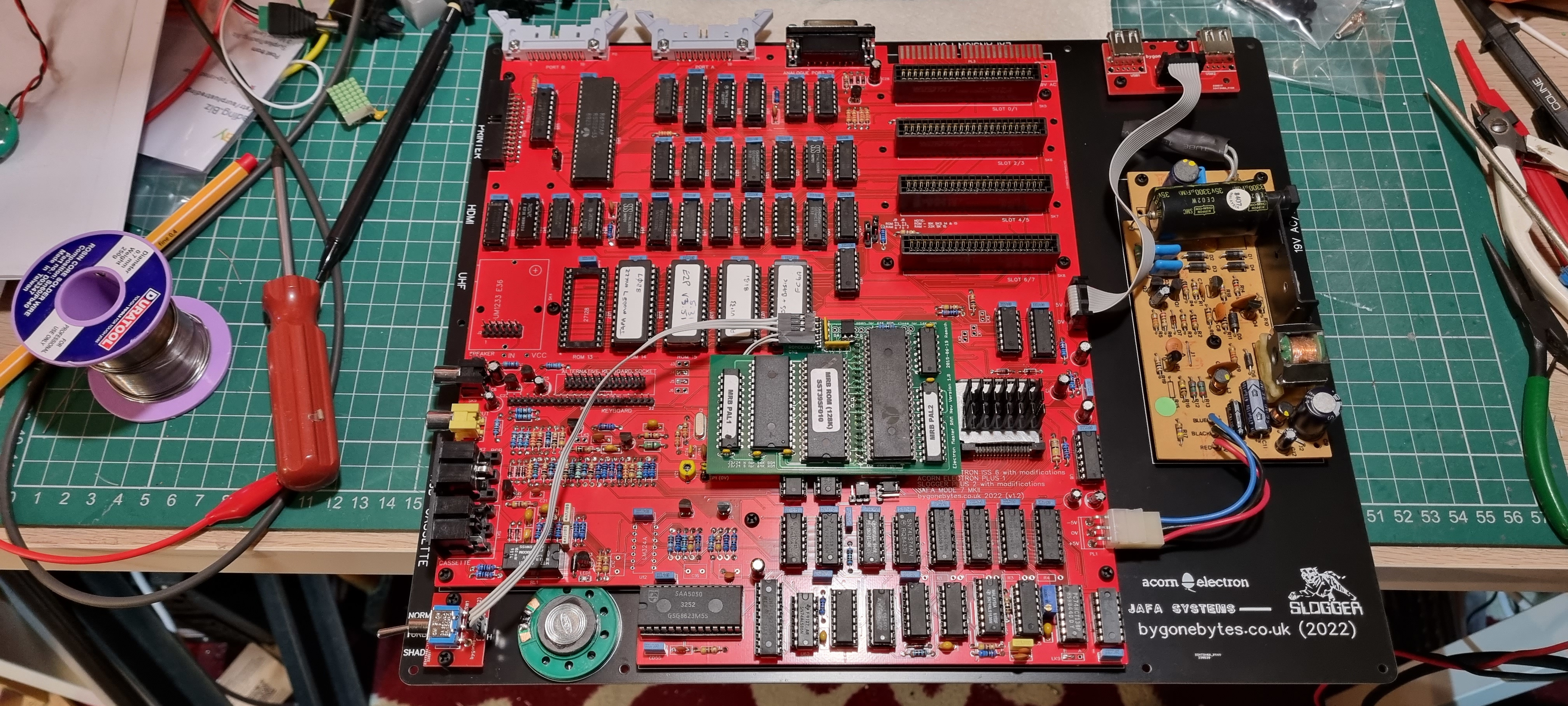
Placing the spacers and mounting the PSU, the main PCB, the speaker, the USB sockets and the MRB switch.
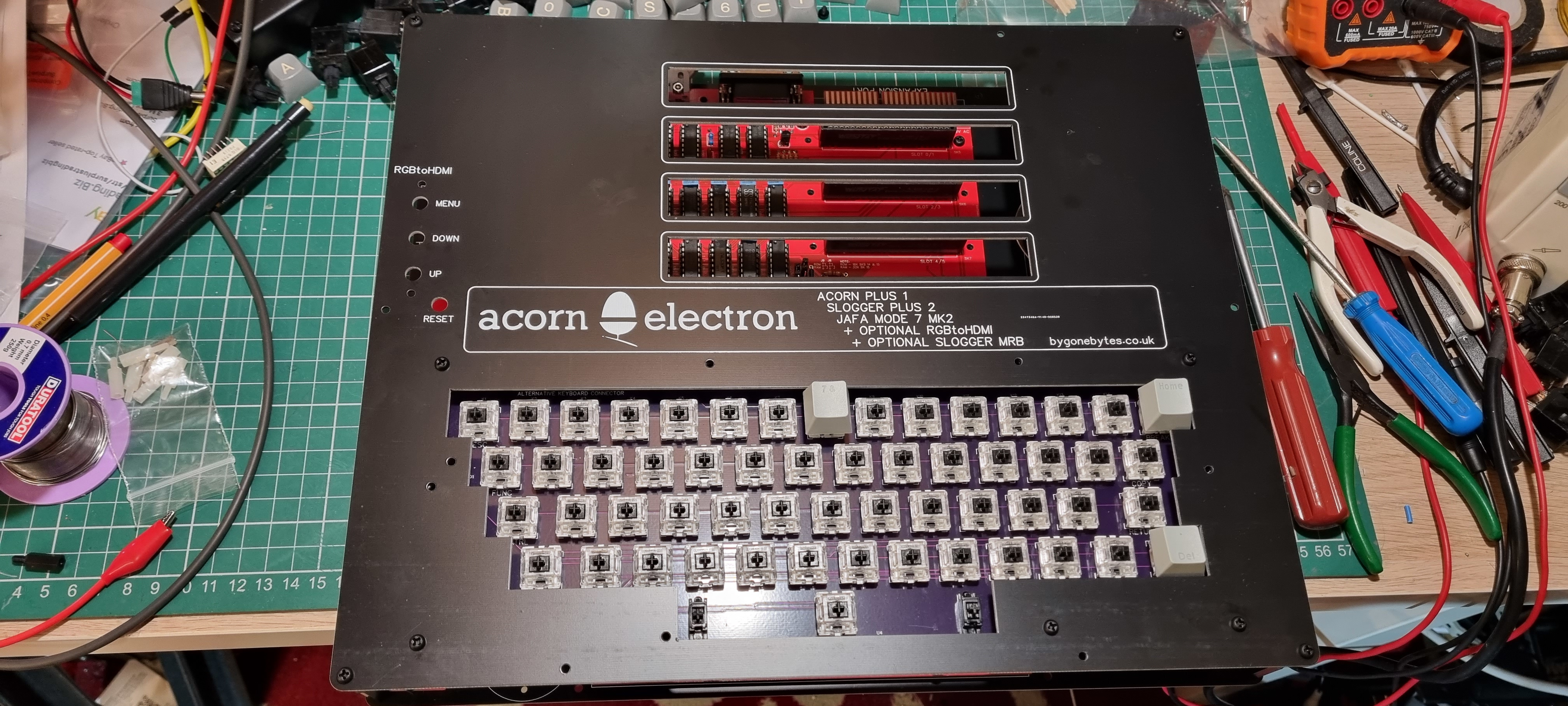
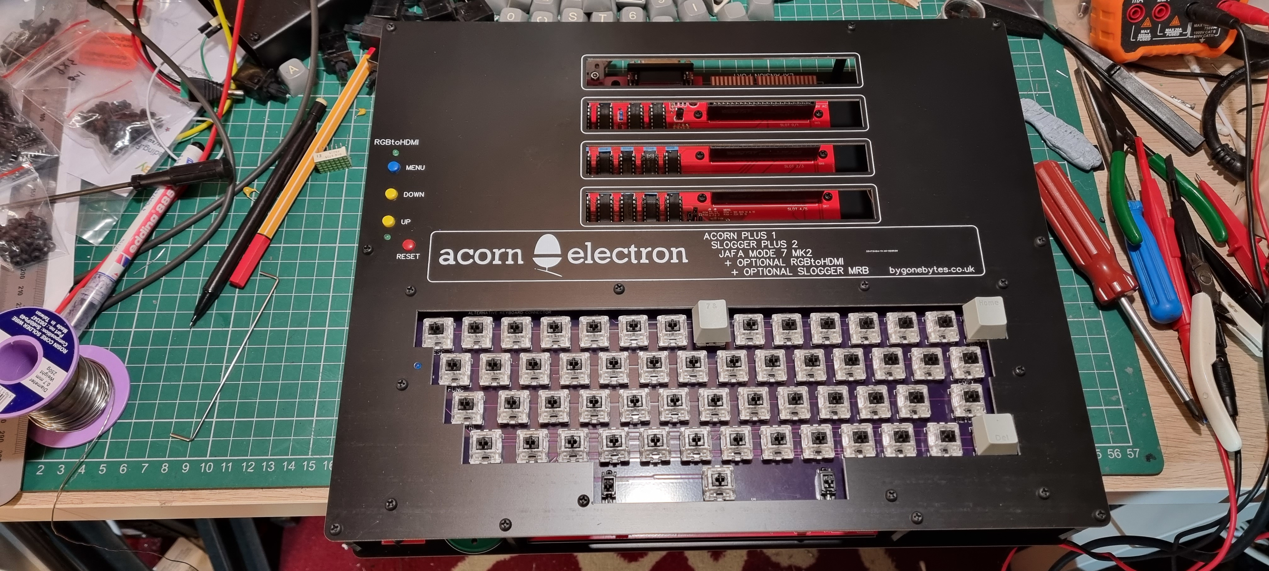
Test fitting of the keyboard to the lid and the lid to the base. I notice I forgot the legends for the composite video and audio!
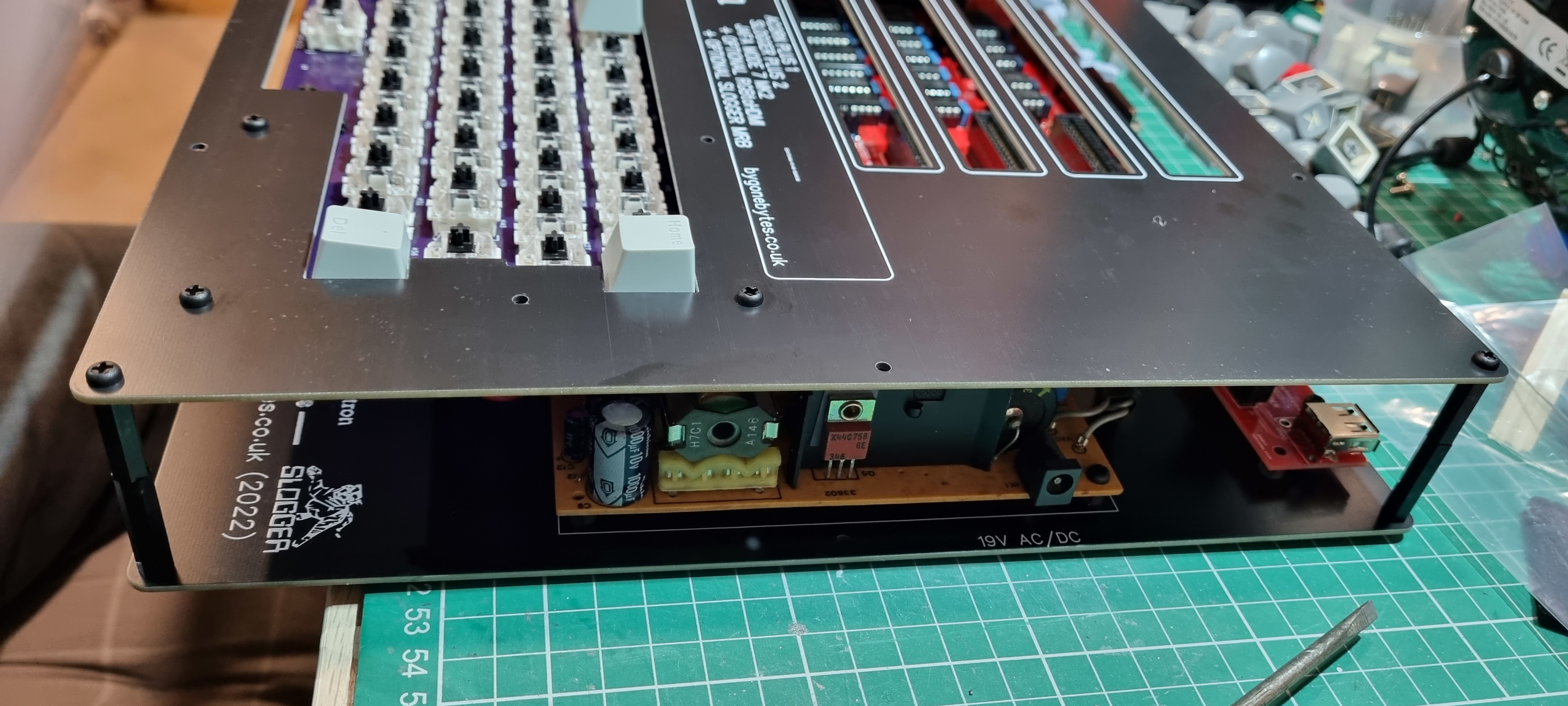
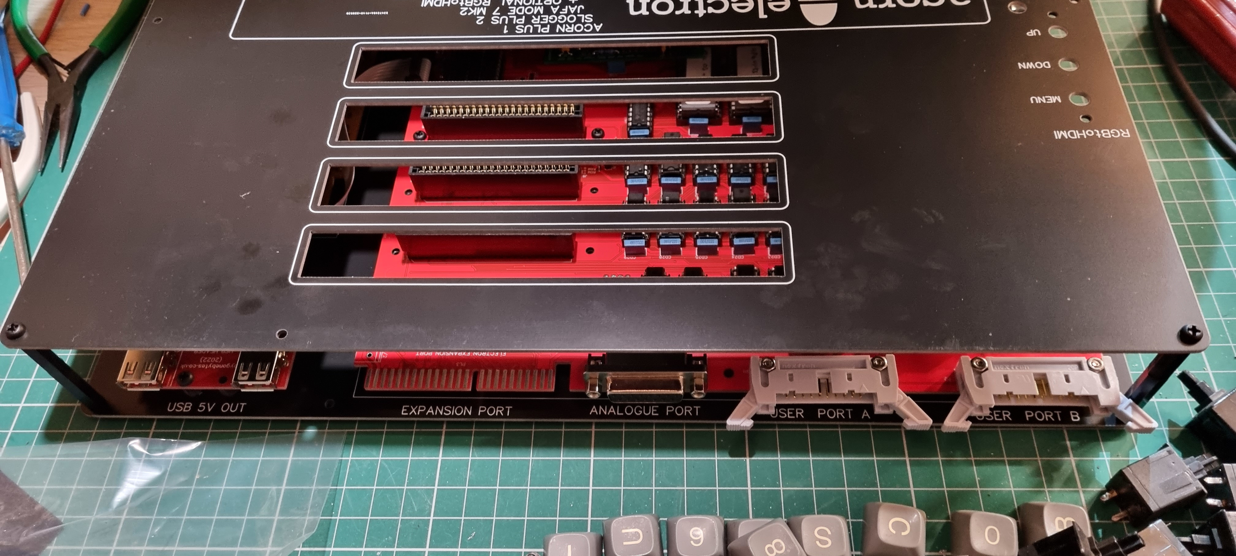
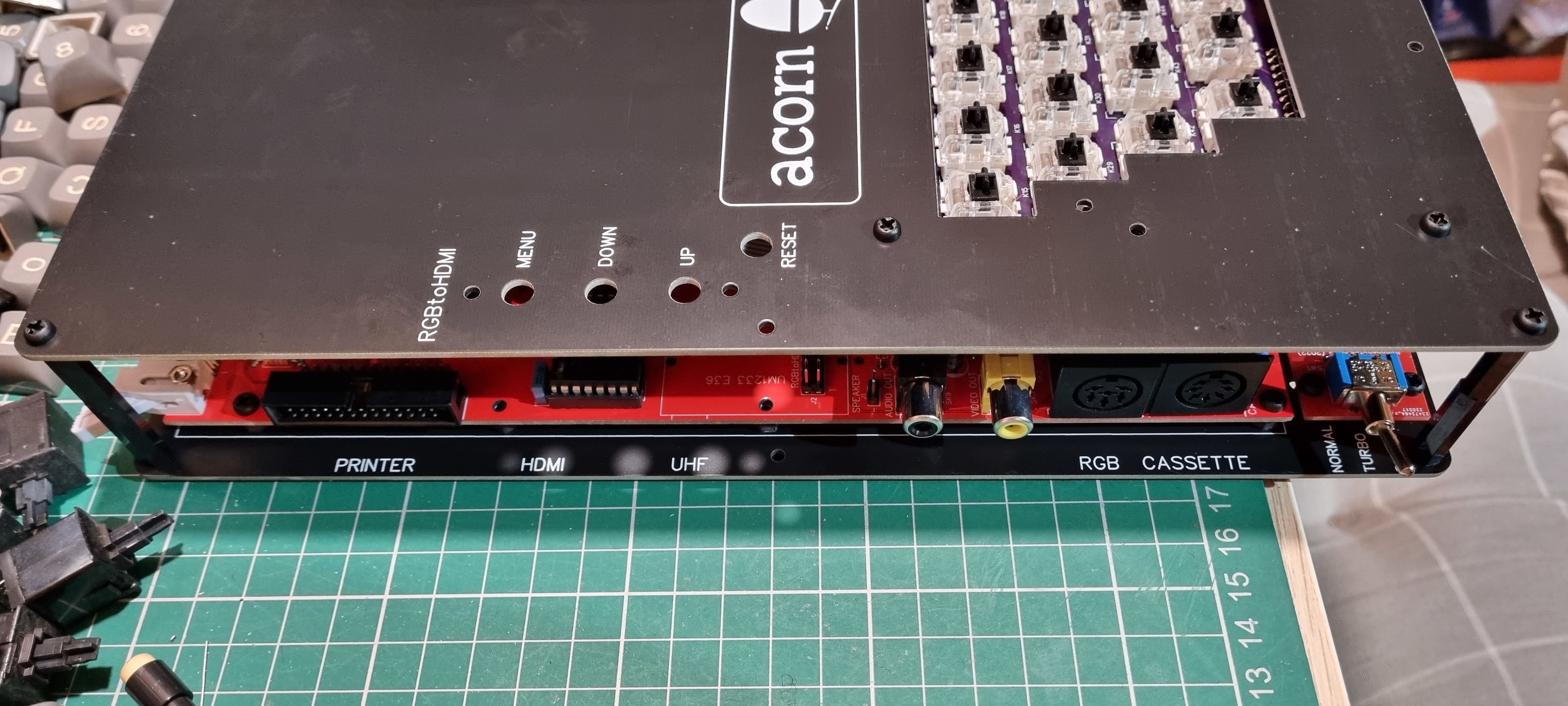
The connectivity..
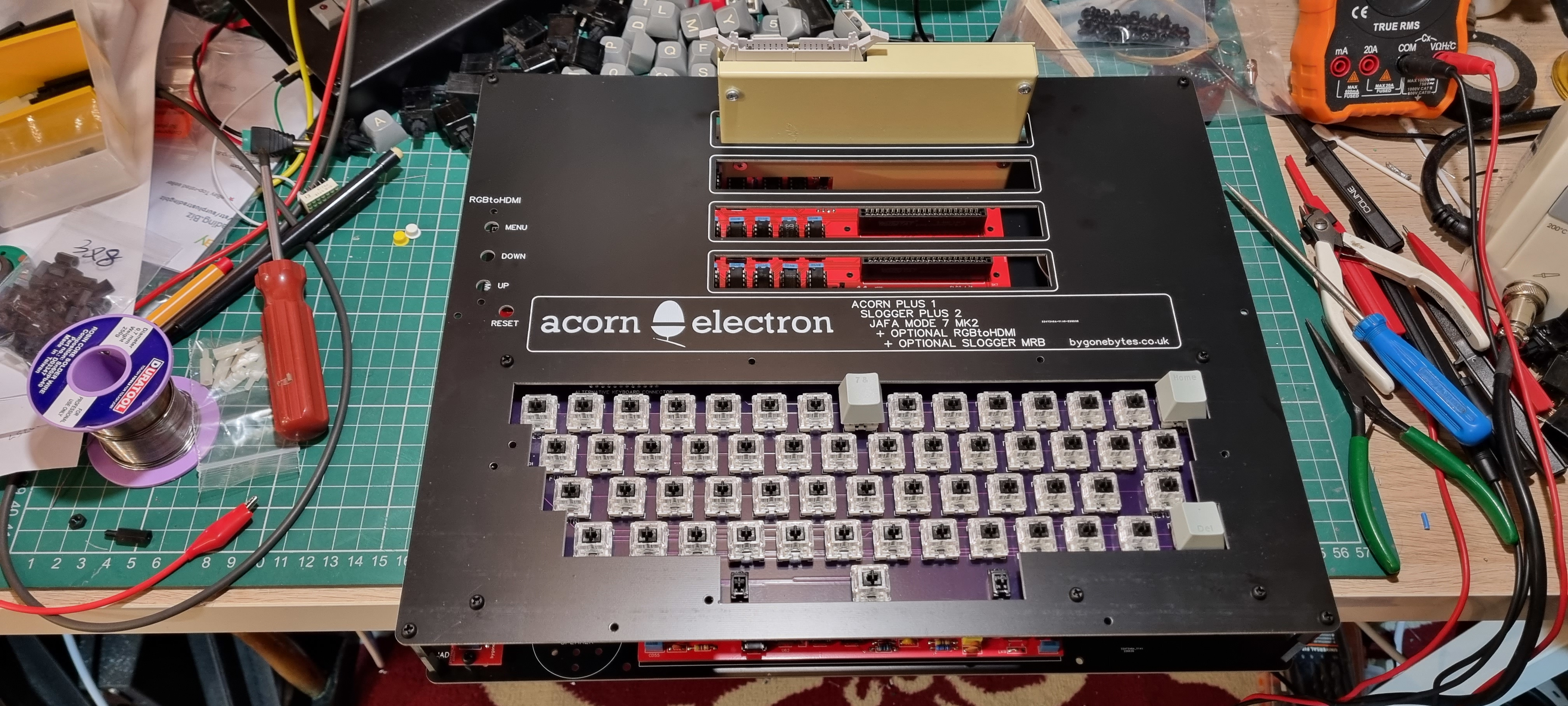
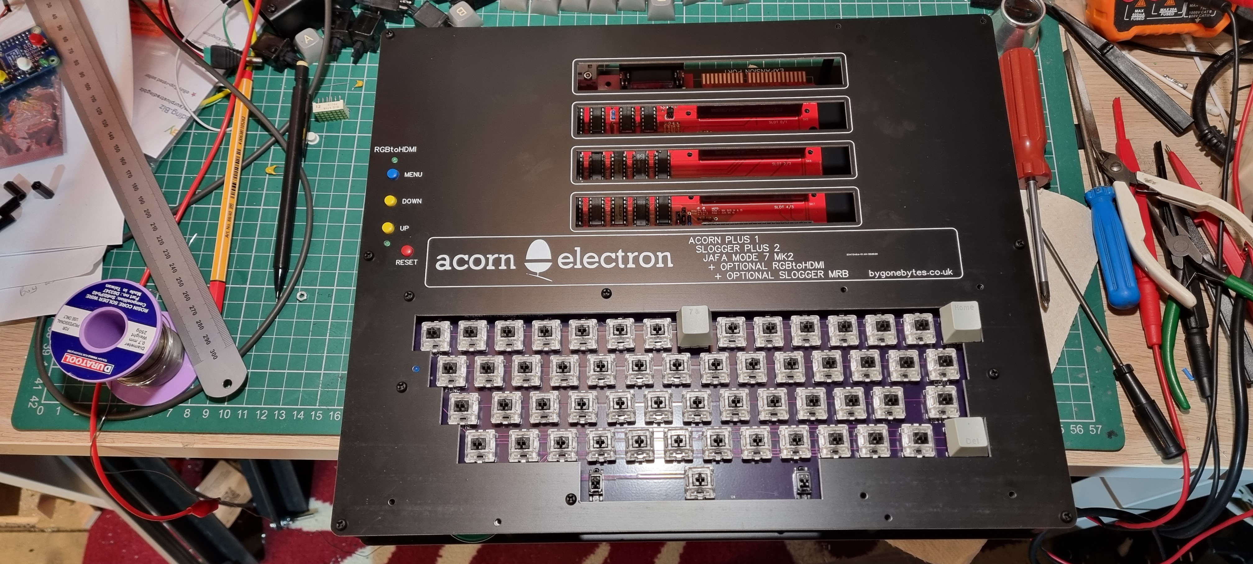
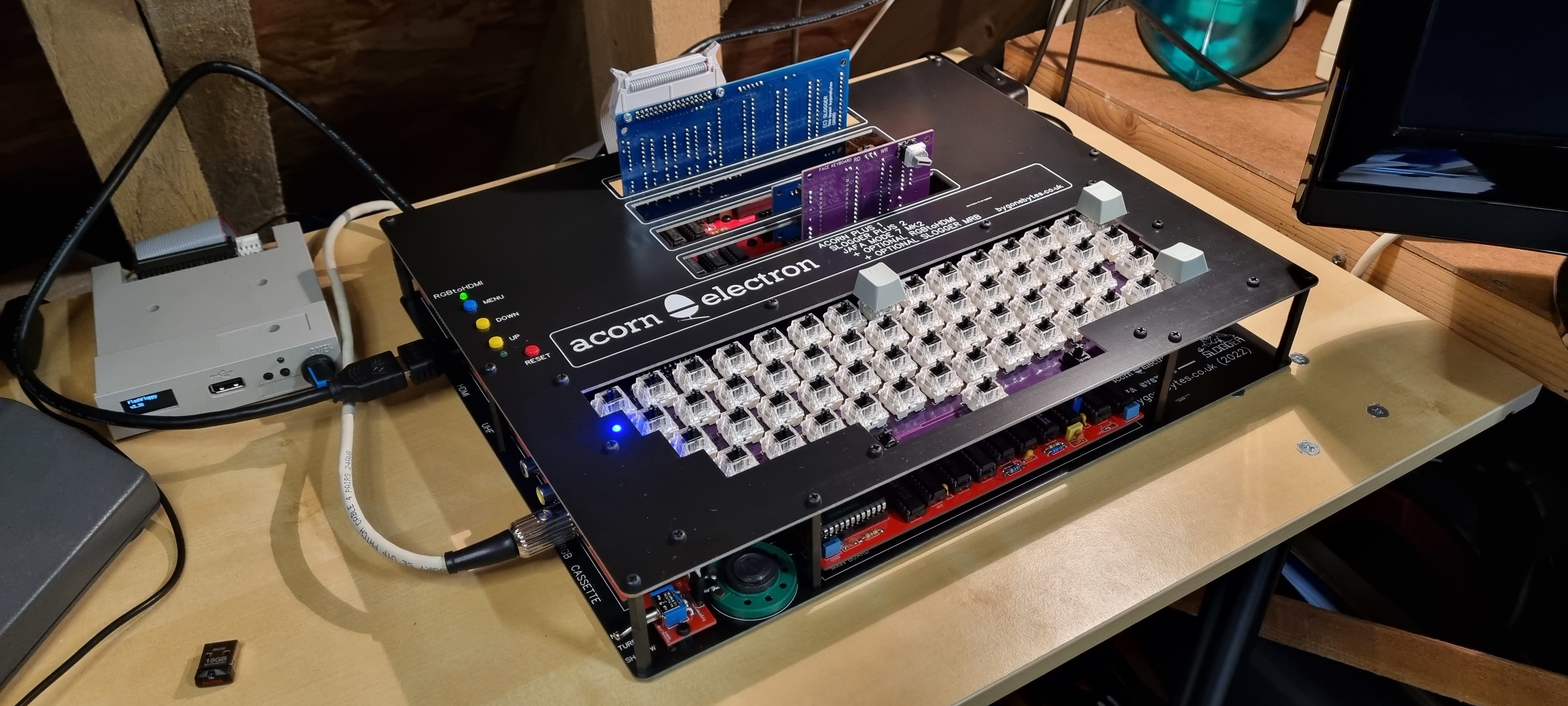
Testing the fitment of cartridges and keycaps. Wiring is finished but the main board will have to come out again as there are few components yet to fit.
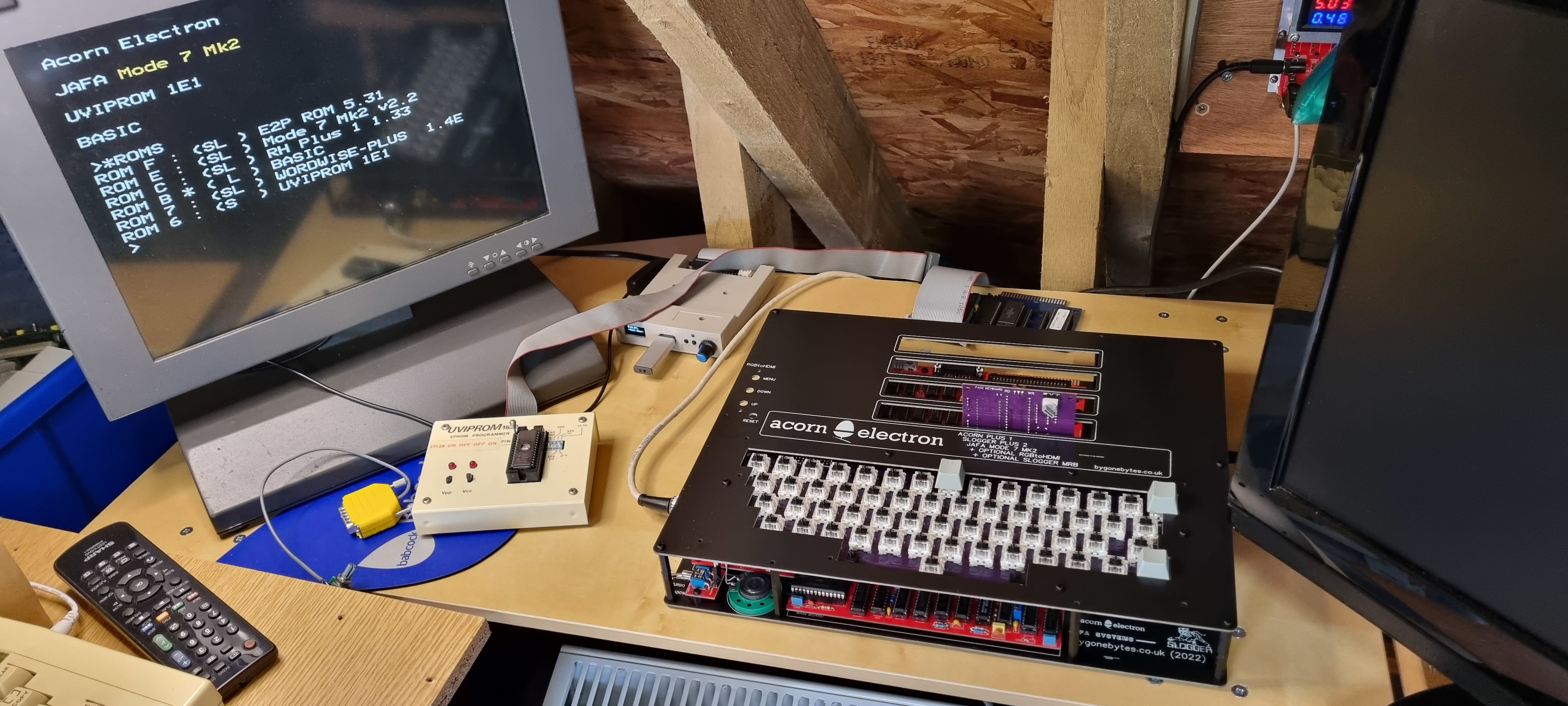
Interim testing, I still have the RGBtoHDMI interface to fit.
Fitting the RGBtoHDMI
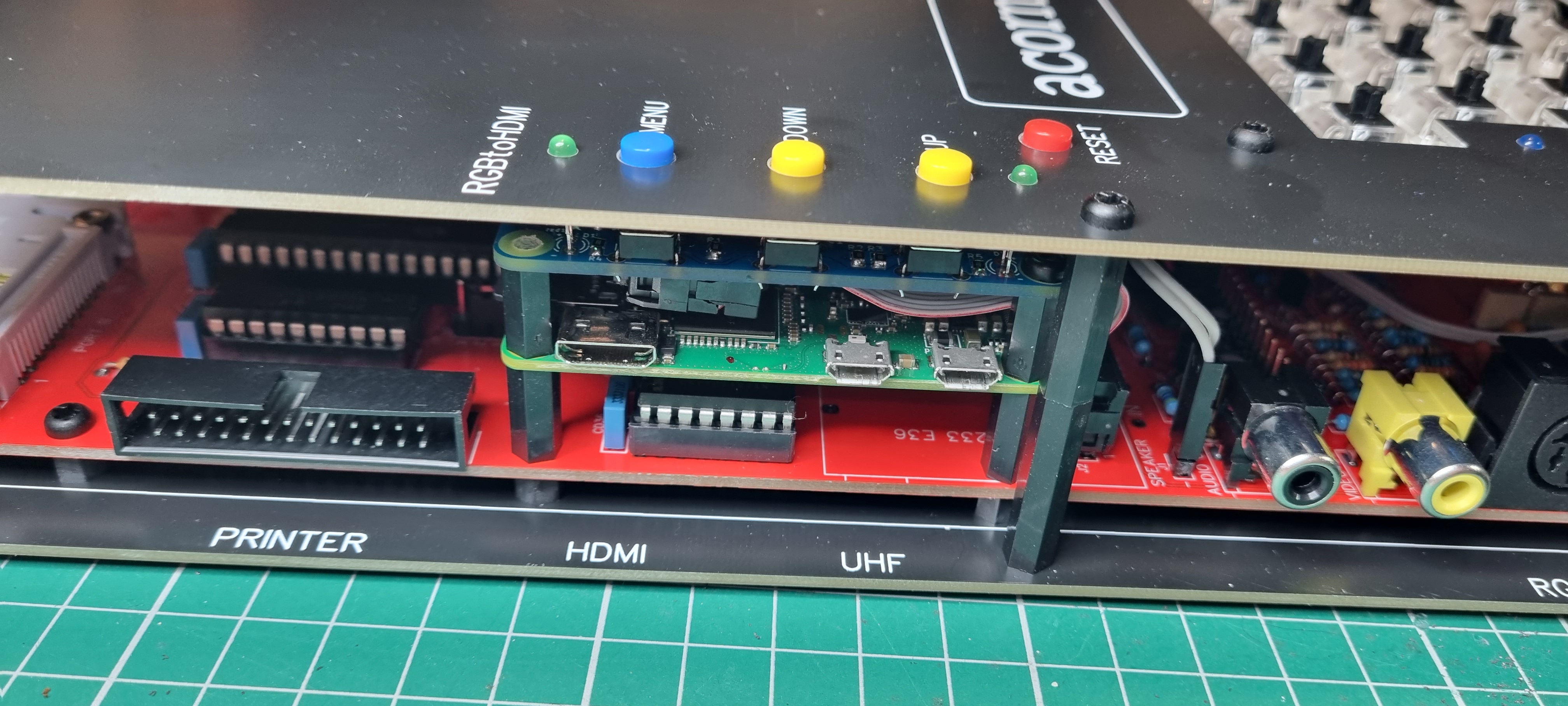
Fitting the RGBtoHDMI took a bit of time as it involved selecting the correct spacer, button and LED heights.
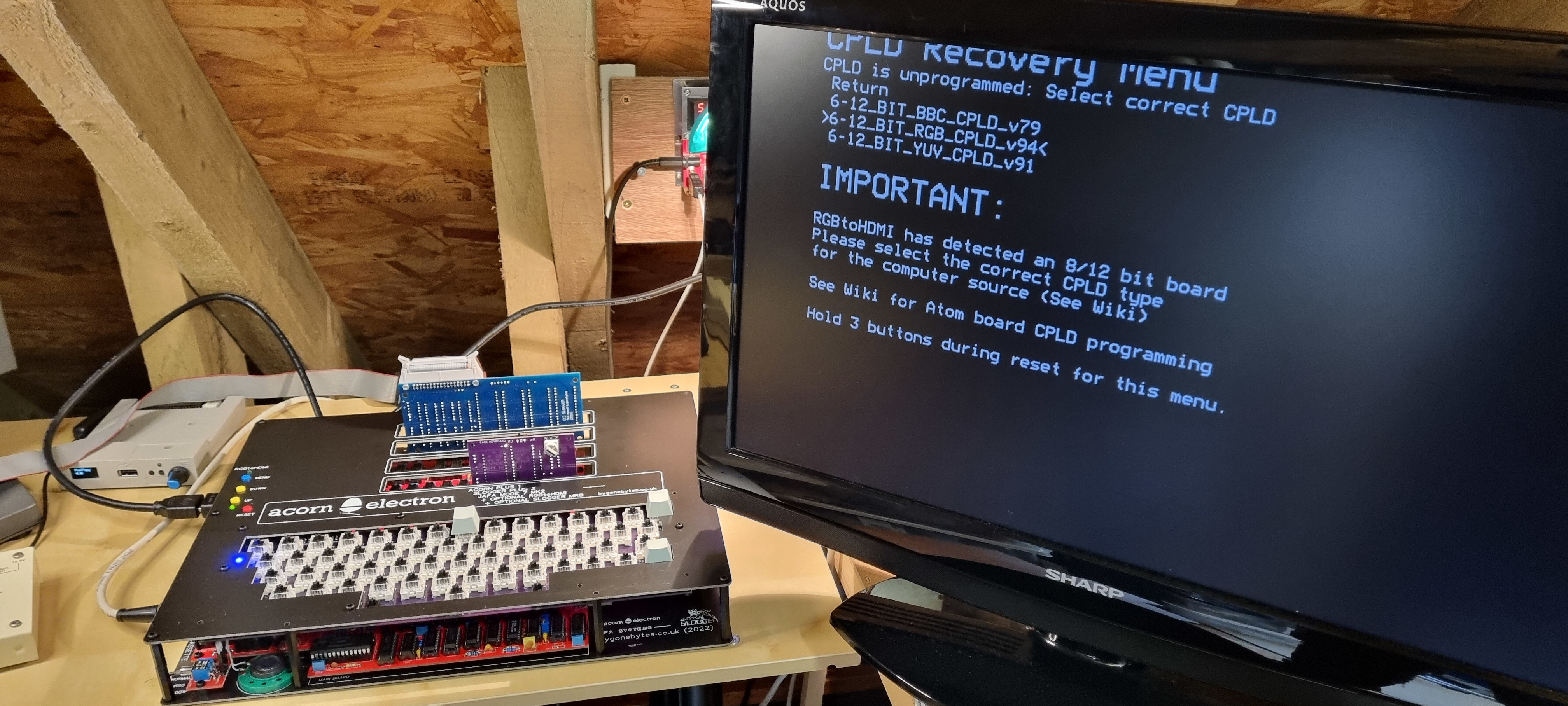
First switch on of the RGBtoHDMI converter and a quick re-calibration to get a perfect picture. The improvements made around the Mode 7/RGB area of the PCB has helped the RGBtoHDMI to generate a good quality output in all modes.
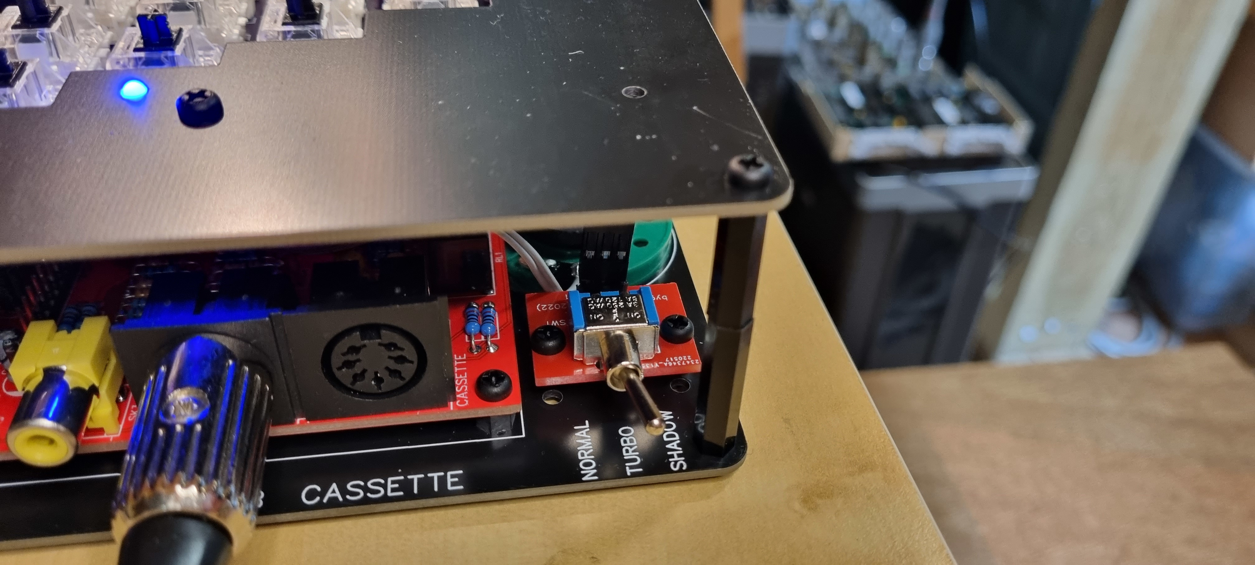
I allowed for two different depths for the MRB switch, moving it deeper into the case prevents it from protruding and it's still easily accessable to use - I was concerned the corner pillar would get in the way. A close up of the cartridge slots and HDMI controls.
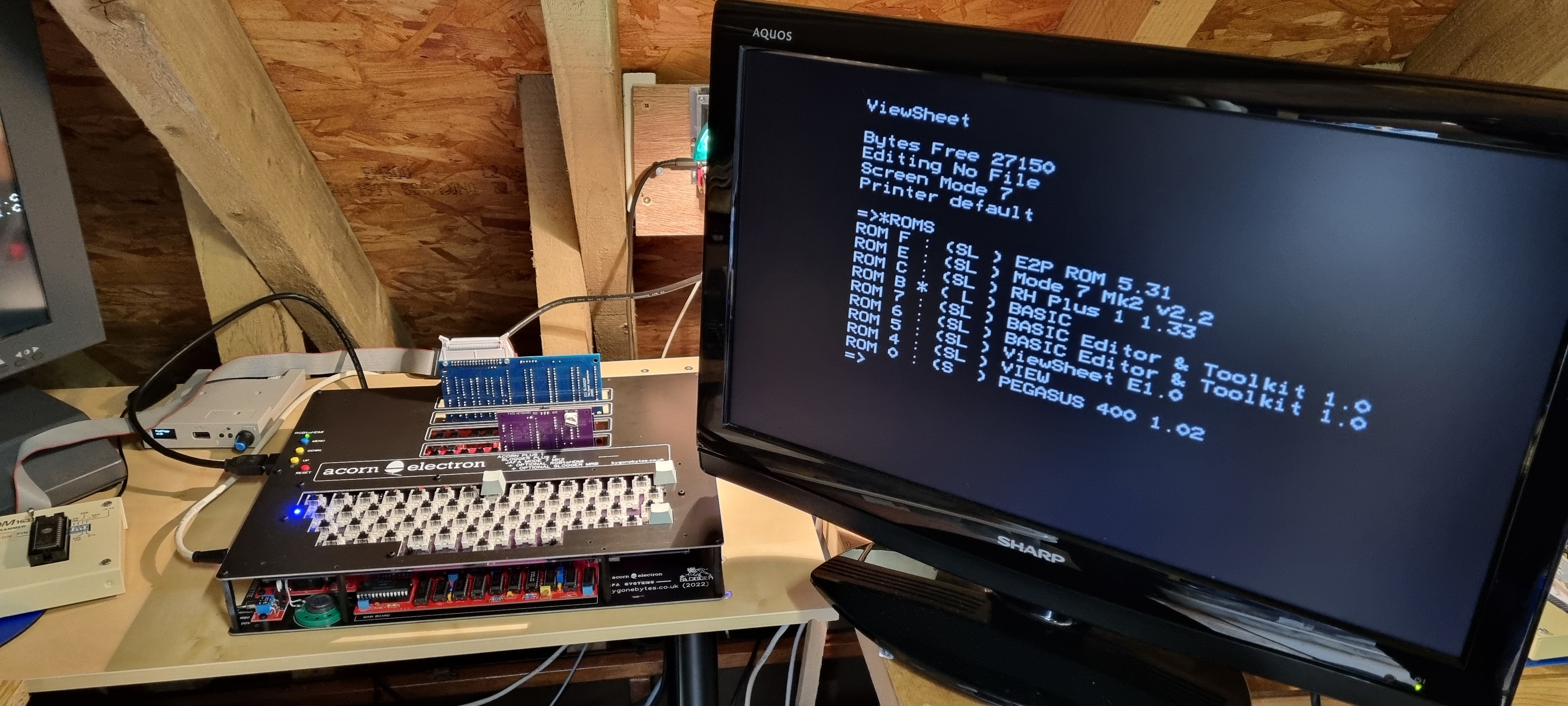
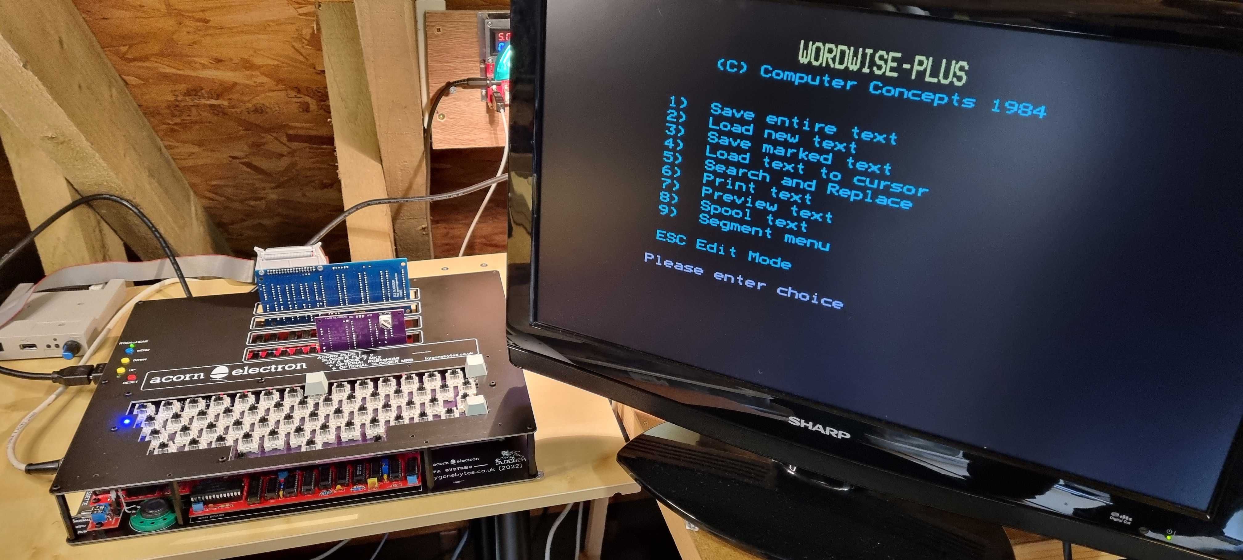
Running nice and smoothly..
What's left to do is to complete the fitting of the LM324 and a couple of capacitors on the main board, fit the new white keycaps and finally screw in all the mounting screws.
That's the last of the components fitted, the LM324 quad op-amp and the capacitors. The PCB is now fully screwed to the base.
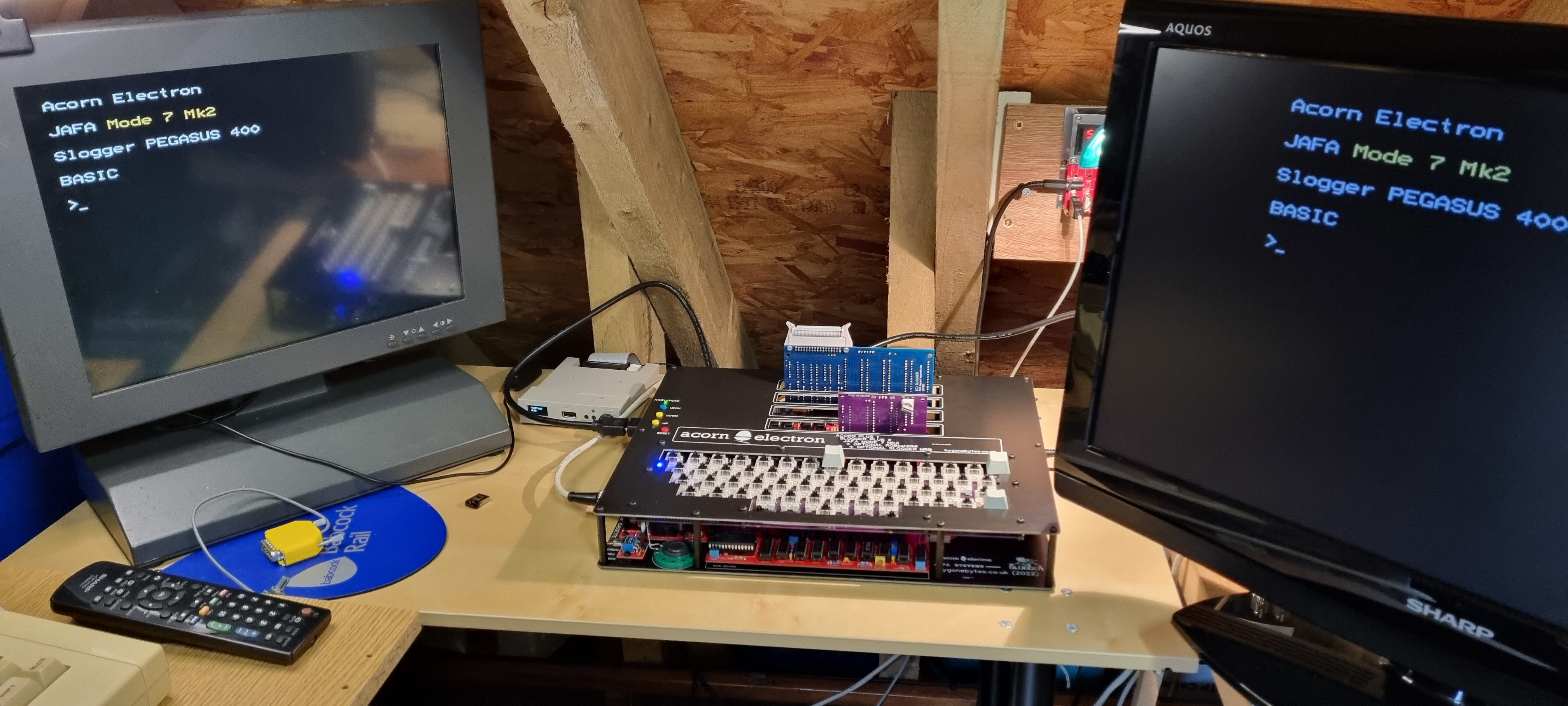
Plugged back into the monitors for final test..just waiting on the keycaps and that will be it finished.
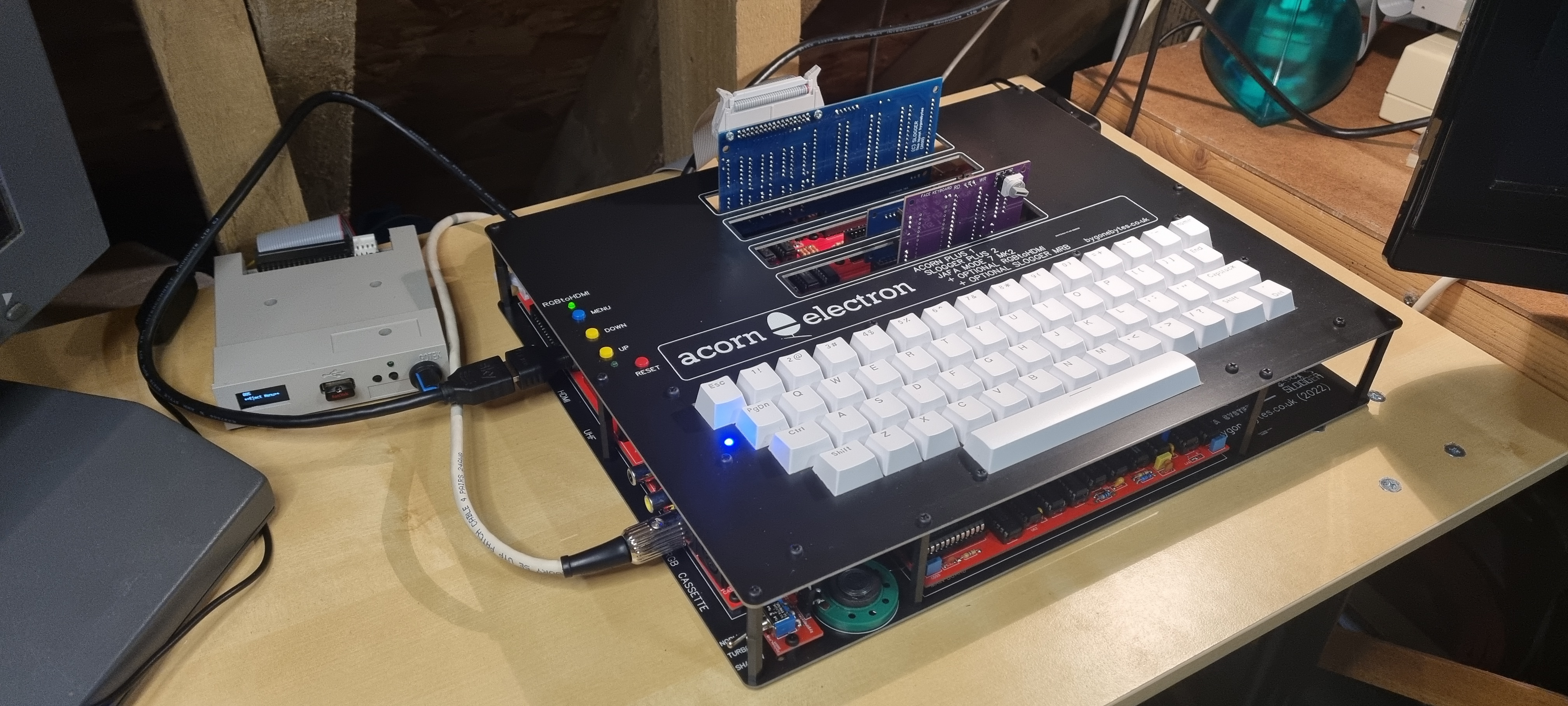
Keycaps on.
One original and three new Electrons.