Introduction
This project of building a clone Electron has been at the back of my mind for the last few years and is finally coming to the fore for a couple of reasons, first I have been looking to buy an Electron and Plus 1 but I have not found any in my price range and second I found I had a few spare ULA chips during my Acorn Revival in 2019. Since then when the odd part appeared I bought it and now I believe I have the enough to make an attempt at creating an Acorn Electron.The first decision to make is the bounds of the project, do I just build the Electron or do I include the Plus 1? Do I also include some of the many addons available? Do I build everything on the same PCB etc.? After some consideration I am thinking my wish list is:
The Electron itself
The Slogger Plus 2 and
The Plus 1
I like the cartridge slot expansion system so having the Plus 1 and Plus 2 will provide four slots and three ROM/RAM banks. This means that all the great expansion cartridges available will be usable and I don't need to think of adding any of their functionality to the board. However there are a couple extras I'd like to add:
A 2x22 header for an IDC keyboard ribbon cable
A header and space for the RGBtoHDMI adapter board
I'll remove the RS423 from the Plus 2 and add a second User Port. The Slogger MRB or OSTC will still be pluggable as before.
So my aim is to have an Electron, Plus 2 and Plus 1 all on a single PCB, possibly on an Mini ATX board size. To get started I'll need to transfer the designs for the Electron, Plus 1 and Plus2. Back in day when I owned a Plus 2 I produced a circuit diagram from the bare PCB so I'll use that but it would need to be checked for completeness.
Looking at the circuits for the various issues of Electrons I chose Issue 6 to use, when redrawing there were a few errors on the drawing that I corrected and removed the single in line memory chip. The Plus 1 was straight forward to redraw and the Plus 2 I also found a couple of errors around the ROM/RAM 14/15 selection. In EasyEDA it took six A3 sheets to complete the design.

Page one of the circuit diagram.
With the design drawn and checked I then imported it into the PCB design area and set out the board size, as I mentioned earlier I am hoping to fit it all into the mini ATX board size of 9.6 x 9.6 inches (243 x 243mm). There are around fifty DIL IC's so it will be a tight fit, I did think about using SMD and/or GAL chips but made the decision to use DIL as it will be easier to fault and replace IC's as and when necessary. I may go down the SMD/GAL route if this board works out.
Once the IC's were all aligned I thought I'd used the auto route feature, at first it seemed to do quite well leaving around 160 nets to manually route. When I started to place the unrouted tracks it became very obvious that the tracks laid down round the ULA by the router just made it impossible to carry on. I ripped up all the ULA tracks and re-laid them in a more sensible layout and carried on from there. Several weeks later I have a layout that I hope will work...

PCb layout after auto routing and after the final track laid down.


Copper areas added and the Gerber View.

3D view.
Keyboard
My first thought was to temporarily borrow one from my Electron but that would be inconvenient and I would have to build one eventually so I made a start on a new keyboard. It will use Cherry MX style keys with generic keycaps, later on I'll think about what to do customising the cap labelling.
Back in the day I had designed a couple of alerations to the keyboard, a SHIFT LOCK and TAB keys but for the moment I'll leave them off but may add them in later. For now just the basic design has been drawn and roughly laid out, I'll wait until the key switches and caps arrive before finalising the PCB.
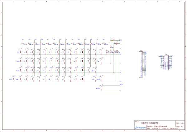
Keyboard Diagram.

Draft PCB Layout.
Keyboard - Draft 2
Contrary to what I said in the last paragraph I have included the SHIFT LOCK and TAB functions on the keyboard, also I have added the FUNCTION KEYS as a separate row similar to the BBC Micro. To achieve this I have included a Raspberry Pi Pico to perform the logic and timings of the two key press sequence for these functions.

Draft 2 PCB Layout.
Keyboard - final design
Changed my mind again, this time it is due to my thoughts on the case design. I am trying to keep the case width and height the same as the original and the extra keys on the draft 2 design would mean a different profile. The keycaps for the Electron are obviously custom made but at the moment I will try to use standard low cost caps. They finally arrived so I could work out the best arrangement and spacing.


Laying out the keycaps and trying out an arrangement on a draft PCB layout.


Another layout tweak and then laying out the caps over the final PCB design. There are at least half a dozen caps that will require a new legend.

I could do an all grey, all yellow or a two tone layout as above.

Final PCB Layout.
Assembling the Keyboard


PCB's arrived and checking keys fit. Soldering the diodes in place.


Working through soldering the keys in place and aligning them.


All keys soldered in and caps on. I'll need to look to see if I can get blank caps engraved.


Testing the keys and finally the caps lock LED. The keyboard is now ready to attach to the Clone PCB.
Assembling the Clone PCB
Gathering all the parts together and basically creating a kit to build. At this stage I don't know whether it will work so my strategy is to solder all the passive components, sockets, transistors, connectors etc. then to test sections of the circuit by adding the IC's. The first area to get working are the two oscillators, 16MHz and 17.7345MHz.
To power it I'll use the perfect PSU, a recycled Electron PSU that I spotted on Ebay a few weeks ago.. plug and play!
With such a large and complex board there will undoubtedly be amendments required to the PCB so I'll catalogue each change as I progress through the build.

The bare PCB.

The kit of parts.

The resistors, diodes and LED soldered in place. First error spotted - I've soldered D7, 8 and 9 in the wrong way round!! not a good start.

Looking more like a populated board with the IC sockets and crystals soldered in place. D7, 8 and 9 replaced.

Add a bit of colour - nearly all the capacitors are fitted. I had a few problems as quite a few capacitors required 0.1" (2.54mm) spacing and most of the capacitors I have are 0.2" (5.05mm), I still have two to fit as I couldn't reduce the lead spacing on my wima 0.2" capacitors. If I ever build a second board I'll buy the smaller capacitors.
At this stage I thought it would be wise to check that there were no shorts on the board. I checked the board before I started using a meter to measure continuity between 0V/5V, 0V/-5V and -5V/5V - all open circuit as expected. This time I powered the board up to check the current draw on the 5V rail, 6mA, this is also as expected with the resistors and capacitors fitted. Excellent no shorts!

With a few more connectors added, Cartridge Slots, Keyboard, Cassette, RGB, Printer and one User Port I started to bring parts of the board to life.
I soldered in the transistors for the cassette motor relay and the printer strobe output then tested both circuits from their respective IC pins - all ok so far. I also measured the Vref for the analogue port, 2.045V. This is as expected as it is created using three diodes in series, 0.7V each = 2.1V. The Plus 1 manual states 1.8V but this would never be the case with this circuit!

I worked out all the link settings and soldered in those that required them, I found the J8 next to slot 3 gets in the way of some cartridges so that will need to be moved. In the mean time I bent it a little to help. I also took the opportunity to make it MRB ready.
Now beginning to populate the IC's starting with the 74S04 used for the 16 & 17.345 MHz oscillators and the counter to divide the frequency down to 1 & 2Mhz.

The waveform (1Mhz) isn't perfect with a little overshoot and noise on the high and low levels. The overshoot may be down to the scope probe I'm using (no tuning) and the noise may not be an issue as it is outside the High/Low logic levels.

Enough components added to test the basic Electron, I'm waiting for a couple of capacitors to complete the cassette interface so that part of the circuit will be tested later.
PSU
Time to power up the ex-Electron PSU to see if it works. Using an old Pi-Top 18V DC power block the unit came up with a good 5.19V but on the -ve supply it was only -3.46V. I remembered that the early switched PSU's required a small load of a few milliamps on the +ve supply for the -ve to regulate so I used my logic probe as a load and the -ve supply regulated nicely at -5.03V.


Back to the build
Power up time! At this point it could go one of two ways - fail miserably or work straight away.


Well it failed miserably with a nice red/yellow screen. Not to worry as this points to one of three things, faulty ULA/Socket, faulty RAM or failed OS/BASIC ROM.
I initially ruled out the ULA and RAM as they are new or previously tested. I downloaded the OS/BASIC ROM image from the internet - taking the lazy route - so I investigated that first. Issue 2 Electrons have the OS ROM in a socket so I had to take one of my systems apart to get access to the ROM to read its contents. The checksum differed from the downloaded version, this is looking positive.. I made a copy and when plugged in and powered on up popped the Acorn Electron banner with the familiar beeps.
Lesson learnt there :)
Next the Plus 1 components..


Components added for the Plus 1 section of the board and on power up shows the Plus 1 ROM is recognised and in the correct bank.

Testing the two cartridge slots with a Pegasus 400 and a Flash ROM cartridge with the Advanced Basic Editor. Both slots are working nicely but there is more to test, the Printer and Analogue ports.


Populating the PCB with the Plus 2 components and testing the cartridge slots, again both working nicely.


Testing the on board ROM Sockets.


Soldering the second User Port connector and the Analogue port in place. Using my user port test program and led driver board to run through a binary count on both ports.

Extending the keyboard cable to make it easier to run more hardware and software tests.
With more use of the board it slowly dawned on me that the volume from the speaker wasn't quite as loud as other Electrons. On investigating this I found that transistor Q2 (Q4 on the original issue 6 drawing) had the wrong pinout. The fault lies with the part I used on the drawing, it's pinout matched quite a few datasheets available on the internet but on checking my Towers International Transistor Selector book (1977) it confirmed my suspicions that the Base and Collector were swapped. Fortunately this was easily rectified by de-soldering the transistor and rotating it but the pcb will require updating. The volume is now somewhat louder!
With the temporary keyboard in a more managable position I can write a few simple programs to test the remaining ports, cassette interface and the Analogue & printer ports.


Testing the Analogue and Printer Ports. I attached a potentiometer between the reference voltage and the analogue input and wrote a simple program to measure the incoming voltage and output it to the screen with a value between 0 and 255. For the printer port I wrote a program that toggled each bit of the port one at a time and used my logic probe to indicate the high/low state of each bit. All working ok.
Now that 99% of the testing is complete and I'm happy with the results I'll start to look at add-ons to try out. I built a spare OSTC card when I did my Electron refurbishment so that may be worth installing or should I go for the MRB? Also the RGBtoHDMI, I bought the parts months ago so it's just a matter of soldering it all together..


Elk Add-Ons
I thought I'd just put the OSTC in to see how it fitted.

As you can see the turbo switch connector is a bit close the cartridge slot, turning the connector in-board or solder the wires direct to the PCB will sort that.
Then the MRB.

The MRB fits quite easliy in place and overhangs the OS ROM and a few 74 series IC's. Unlike the orginal Electron motherboard I put all IC's in sockets this has the effect of raising the components closer the the MRB. Although the MRB fits I thought it would be prudent to add a 40 pin socket to improve clearance.
On the original Electron the MRB was a tight fit between the keyboard and the processor so when I'm building the case I'll need to take this into account.
And I built the RGBtoHDMI:


The RGBtoHDMI worked no problem but it did highlight an error on my PCB as you can see by the red display. I must have had a brain storm the day I did this part of the cicuit as I missed the blue off the header and put red where it should be blue. To solve this on the prototype board I had to run a wire from the blue output to the J2 header and cross a couple of wires on the ribbon cable. Once that was done I got this:


All correct now.


Just checking the linearity, circles circular! and a photo with the add-ons attached - I hope the Elk PSU can cope with all this!

Soak testing with AMX Stop Press.
Bringing the keyboard and main board together

Last bit of wiring is to press a ribbon cable for the keyboard. Unfortunately the 24 pin IDC headers haven't arrived and being impatient I used a couple spare 26 pin headers.

The good news is that all the keys are in the correct place and feel good in use. The ribbon cable provides a much neater and more robust connection between the main board and keyboard but the downside is still the keycap legends...more thought and research is needed.
A couple of days later I replaced the ribbon cable with the correct 24 Pin Headers....and the donor Electron has its keyboard back.
The Case
There are many ways to make a case but my prefered method is to make it with sheet aluminium as it is very easy to work with. I did think of using thin plywood just to give it that modern retro look and I may yet make one this way but first I will start looking at dimensions and clearances.

I installed the MRB with an extra socket underneath to improve the clearance above the main board IC's but as you can see it stands fairly high. This will affect the height of the case so I took this photo to see if I could reduce the clearance.
It can be seen that if lowered the MRB the ROM socket pins would touch the IC pins below so out came the board and all the pins on the underside were trimmed. This allowed the extra socket to be removed and the board now sits neatly above the the IC's.

Sketching out the basic shape of the case base including clearances for the keyboard/MRB.

Cutting the aluminium to shape.

and folding it into shape.


The case is the same width but only 20mm deeper than an Electron with a Plus 1, nice and compact.
Drilling and hole cutting:


Drilling the fixing holes in the base and the holes for the cassette, RGB, video, audio and printer port.


Now the cut-outs for the user ports, analogue port and the edge connector.


Marking out he holes for the MRB switch and speaker.


I had to modify the holes for the video and audio connectors as they were preventing easy fitting of the PCB in the case. These connectors should be pushed back deeper on the PCB to make them almost flush with the edge.


Placed the keyboard in its rough position to see how it will look. Mounting the PSU, I pushed it a bit deeper in the case to ensure there is no fouling of the keyboard. I have also added a USB socket to power a Gotek drive.


Everything in situe. Now to dismantle it to prepare for painting.
Painting


I used the Rust-Oleum Painter's touch Ivory silk Satin Multi-surface Decorative spray paint. It's a very good match to the original Electron colour.
Assembling


I started by fitting the PSU, I tapped off the 5V under the board for the USB Gotek supply. The main board fitted in neatly and I added an extra spacer under the RGBtoHDMI to provide midway support for the board when inserting EPROMS.
Powering on to check it all still works and setting the RGBtoHDMI screen resolution for the monitor.

Comparing case sizes..almost the same but with a Slogger +2 included..
Carrying on with the case design - the lid. I will split this into two parts, the front (keyboard) and the rear (cartridge slots). The reason for this is to give easy access to the Slot/ROM portion and also if I ever want to change the keyboard to a genuine one then it's a much smaller job to replace.


The folding turned out to be a bit more complex than I thought but it looks good.

I will now mark-up and cut out the keyboard space then prepare it for painting.


First fit after cutting out the keyboard space and then trying it out before filing, brushing and cleaning for painting. I've temporary used bolts to hold the keyboard in place, the final ones will be counter sunk and painted to make them less noticable.


I couldn't get used to the yellow keys so I've changed them for grey. I'm waiting on counter sunk screws and spacers to finish mounting the keyboard and I've folded the last piece of the case. My plan was to cut the cartridge slots folding the excess material in to give a nice finished edge and to add strengh to the lid but it was to difficult to do with the tools I have so I cut the slots completely.

The case is almost done, just the keyboard spacers and bolts to finish off the mechanical side then maybe add the Electron decal. I'm not keen on the look of the cartridge slot cut-outs, it may be possible to add a bracket internally so you can't see inside. I suppose it has the look of a Slogger Rombox Plus. Oh! and that missing SHIFT keycap should arrive soon.

Just after getting the case finished the Electron failed!! The symtoms were normal background with randomly moving pixels on the screen. I checked the mode it was in - Shadow Mode, then I tried Turbo - same effect, then Standard - failed completely, yellow/white rectangles.
This pointed me towards faulty on board RAM as it was more or less working in the MRB turbo and shadow modes (MRB's own RAM). Luckily for me the first RAM chip I replaced fixed it. It's time to do more soak testing so I have populated the four cartridge slots with a Pegasus 400, an ATI with Pi 2nd processor, a Flash ROM board and my BBRAMextreme card. I'll leave it running to see if there are more early part failures.


Working toward finishing up on this project. The missing key cap arrived and I thought I'd see what it would look like if I made the number/functions keys red, BBC Micro style, but I'm not sure I like it.
I added a Gotek, it's one of the new type so it's a bit different inside but easier to modify. I measured the current drawn by the Gotek, 22mA and with a USB stick 82mA. The Electron PSU can cope no problem so my mod to include a USB port makes the installation quite neat.
I started to load the extreme catridge with some ROM images and trying out AMX Stop Press.
Decal

While I'm waiting for parts I've been editing a decal for the case. So far I've kept it similar to the original..
Finished!

....
Log
Note - all component numbering is unique to this board.
(1) Silkscreen - missing voltage values for power supply socket
(2) Silkscreen - R84 name to be repositioned
(3) Power Supply Connector holes require enlarging
(4) Mounting holes for cartridge slot connector require repositioning (I'm not using that type of connector so not an issue at present)
(5) Look at the lead spacing on C12, 13, 14, 18, 19, 20, 23, and 27
(6) VC1 increase hole diameter
(7) C16 should be 0.2" spacing
(8) Cassette socket holes require enlarging
(9) Silkscreen - speaker link polarity labelling missing
(10) Silkscreen - move names for LK4, LK7, LK8
(11) Silkscreen - number pins on J7
(12) Silkscreen - number pins on LK1NF
(13) J8 gets in the way of some cartridges - move
(14) Update Q2 pinout
(15) Fix the pinout of J2, the RGBtoHDMI header socket
(16) J7 pin 1 not connected - bad label on drawing.
(17) Additional mounting holes are required near the ROMs and Processor to support insertion and extraction.
(18) Re-position the video and audio connectors deeper on the PCB.
(19) Silkscreen - U28 reads 74LS139 should be 74LS260, parts list correct.
(20)