AP6 - Advanced Plus 6
One of the first upgrades I made after I decided to revive my Acorn computers in 2019 was to install an AP6 ROM board, luckily they were still available from Retro Hardware, so I ordered a kit and set about assembling it. At the time I felt there was little point of documenting the assembly as the manual provided a very comprehensive set of photos.
In the last few months I have added quite a few Electron addon assembly projects so I thought I'd add the AP6 photos I took back in 2019. I also added a couple of battery backed RAM modules to the AP6 giving the Electron a ridiculous number of RAM banks.
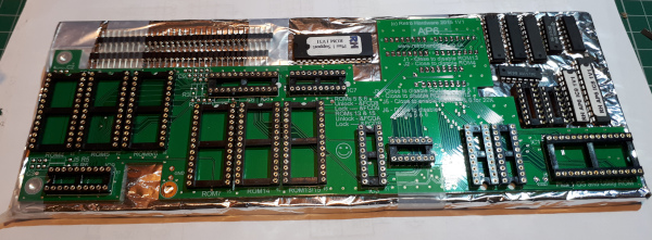
The kit as it arrived.
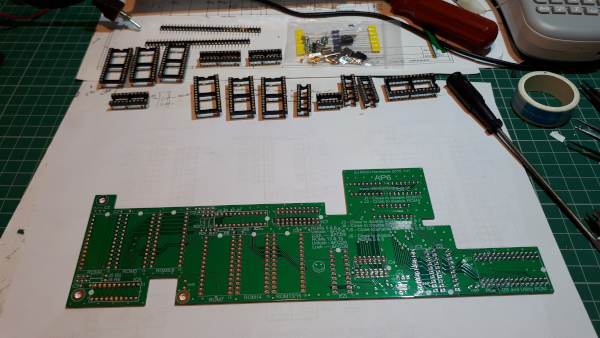
Laying all the components out.
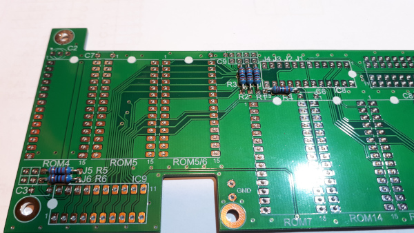
Soldering the resistors.
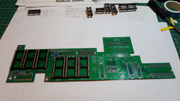
Inserting the ROM sockets.
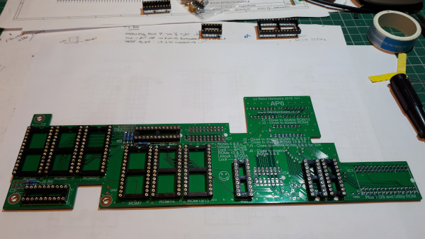
More sockets.
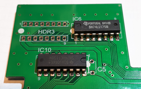
Soldering IC6 and IC10.
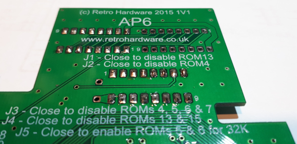
making sure the legs are cut as short as possible.
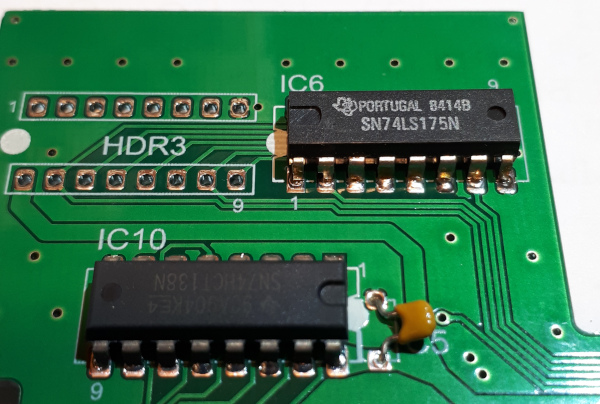
Solder the decoupling capacitor.
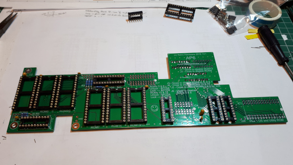
then all the others on the top side.
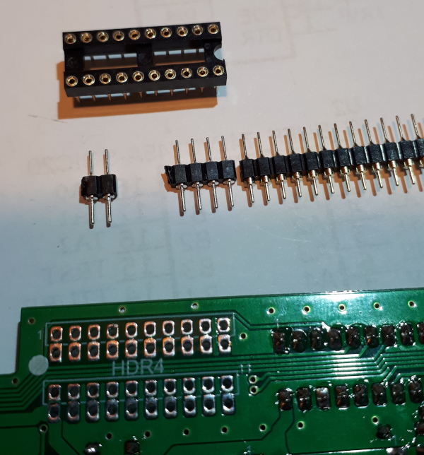
IC headers
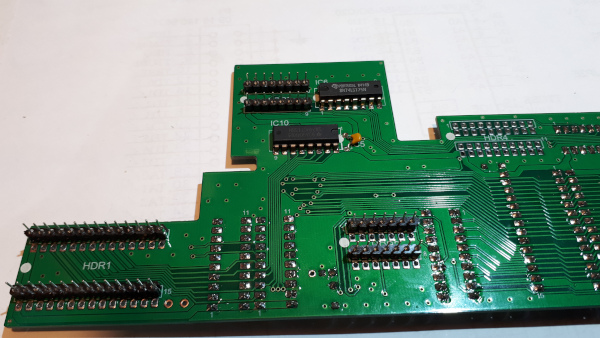
Soldered in place.

Link headers
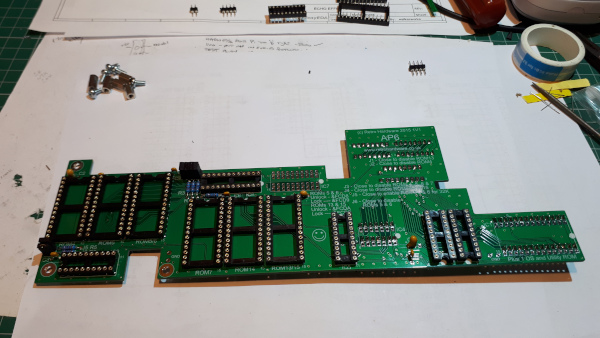
Soldered in place.
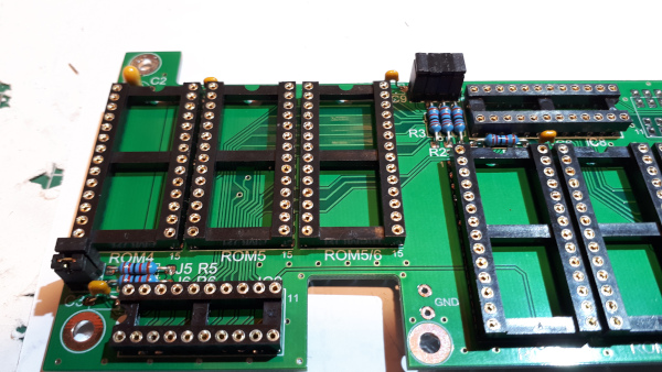
Close up of links.
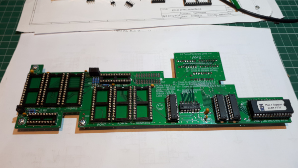
Inserting the buffer IC's.
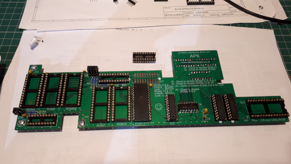
Setting the Links and inserting a Flash memory IC.
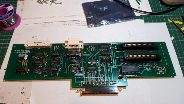
The Plus 1 removed from its case.
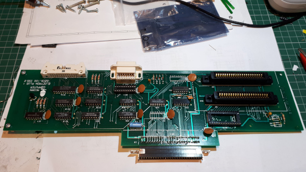
Removing IC1, IC6 and IC11.
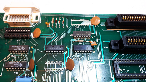
Close up of IC1/6 board area.
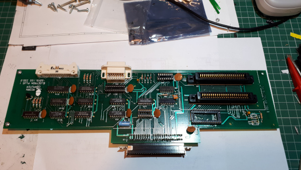
Soldering in IC sockets for IC1 and IC6.
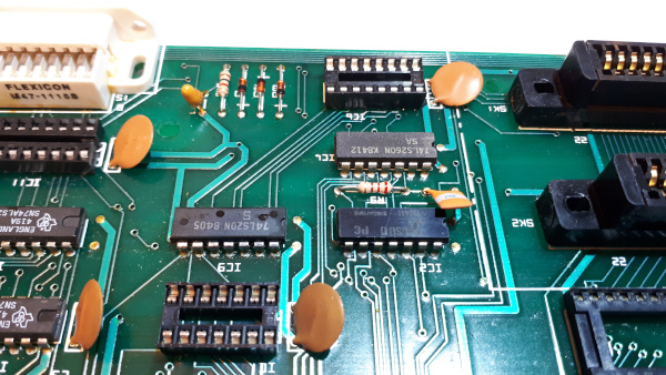
Close up ob board area with IC1 nad IC6 sockets showing the decoupling capacitors gently bent closer to the PCB.
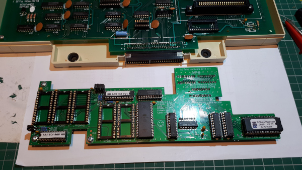
The AP6 and Plus 1 ready for assembly.
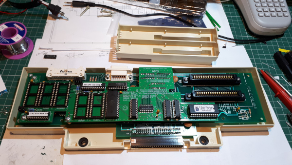
The AP6 plugged into the Plus 1.
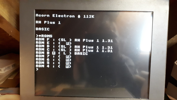
First test showing there is a problem - ROM titles reflecting down the list. This was sorted by replacing the 74HCT245 in socket IC5 with a 74LS245.
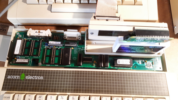
Further testing with the AP3/4 and ABR plugged in the Plus 1 cartridge slots.
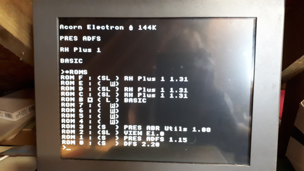
The ROM list, still showing the reflected titles problem..this was fixed later.
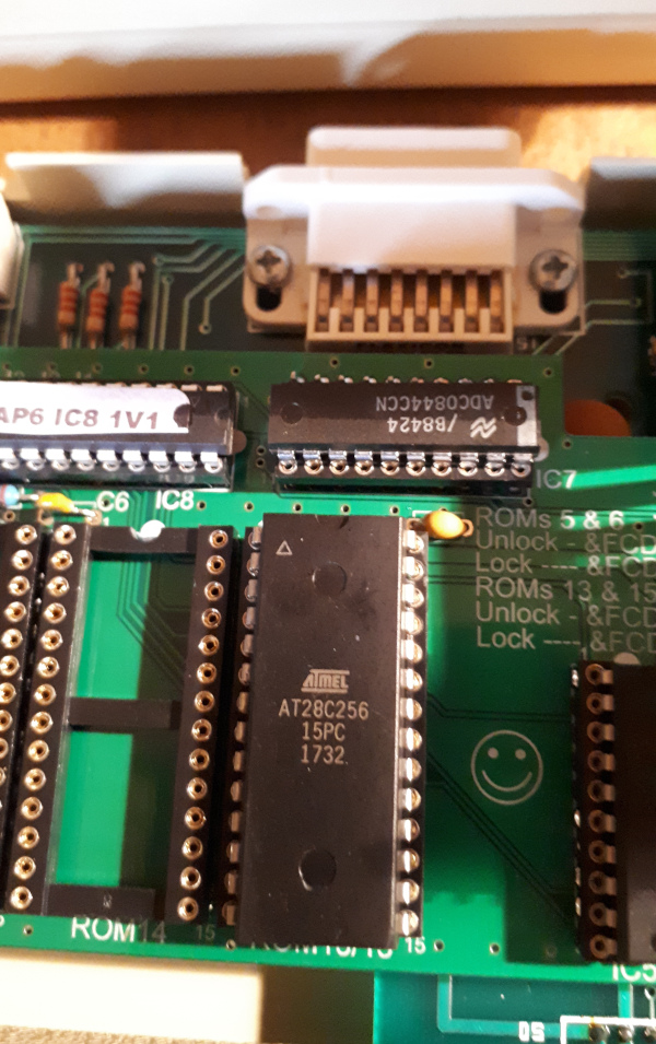
Close up of Flash memory IC in banks 13/15.
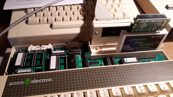
Adding more ROM's.
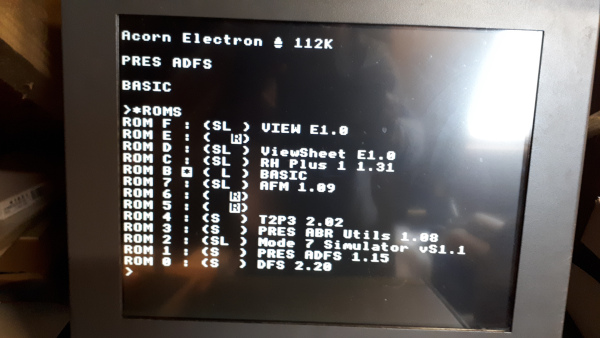
ROM list.
Battery Backed RAM
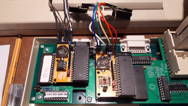
The right hand Battery Backed RAM was a remake of my module from the 90's but it didn't hold up the memory for more than a couple days, the battery was far too small! The Battery Backed RAM module on the left is an updated version using a battery management IC. The two modules provide space for 32 ROM images.
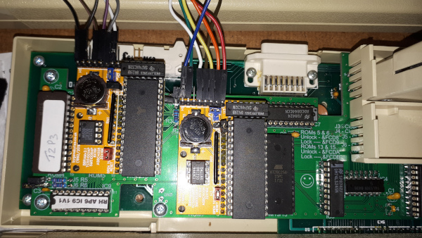
Two new RAM modules in place.
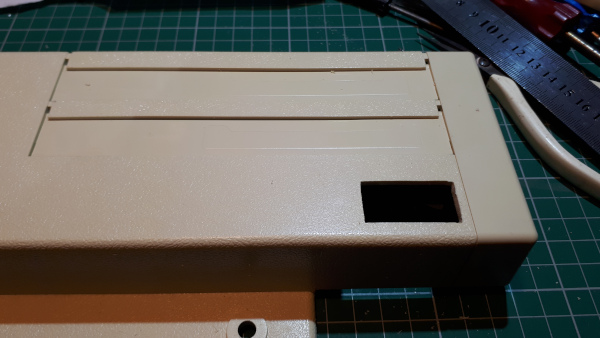
I cut out the slot for the RAM bank selection switches.
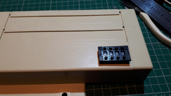
Switches being inserted.
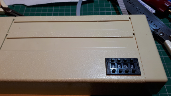
Switches in place.
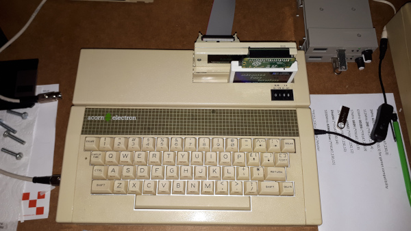
The Electron not quite finished, no R/W switch yet, but it shows how it looks put back together.
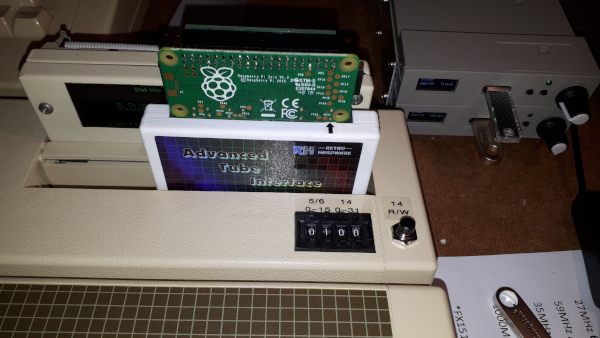
Write protect switch added for bank 14. Banks 5/6 have software write protect provided by the AP6 support ROM
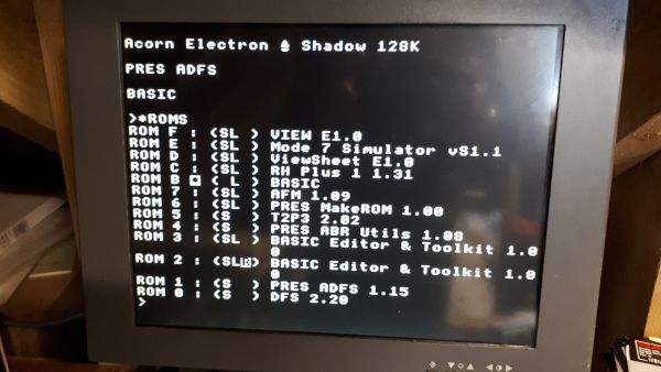
RAM banks fully loaded.